
External combustion engine

a technology of external combustion engine and combustion gas, which is applied in the direction of steam engine plants, machines/engines, mechanical equipment, etc., can solve the problems of engine's characteristic slow start, delay in transferring heat energy from the combustion gas of the fuel, and other drawbacks of the external combustion engine, so as to reduce air pollution, reduce volatility and flammability, and be safer to handle

Inactive Publication Date: 2007-08-28
ROBERTS JOHN HAMLIN
View PDF30 Cites 20 Cited by
  • Summary
  • Abstract
  • Description
  • Claims
  • Application Information

AI Technical Summary

Benefits of technology

[0009]The advantages of the improved external combustion engine of the present invention include better combustion and lower pollution, especially with regard to nitrous oxides and carbon monoxide, relative to an internal combustion engine. The external combustion engine may be powered by a wide variety of fuels, which provides greater versatility. Another advantage of the present invention is that it employs relatively low boiling temperature fluid, for example as compared to water, which makes it possible to insulate the components of the engine against heat loss, without the risk of the insulation melting or combusting. Further, the relatively low operating temperature of the present engine means that it is easier to maintain lubrication of the moving components of the motor.
[0010]The foregoing objectives, as well as other advantages and benefits, are met by the hereinafter described engine and method of its use.
[0011]An organic Rankine engine may be generally characterized as follows. An organic working fluid circulates through a closed system, where it is heated by an external source, vaporized, introduced into a motor to produce work based on a pressure differential between an intake port and an exhaust port of the motor, condensed, and then returned to the boiler, to repeat the cycle. At all times, the working fluid is contained by the equipment and tubing / piping connecting the equipment, and is not released to or in contact with the ambient air, that is, it is a closed system.
[0012]The boiler is capable of exchanging heat between the working fluid and an external heat source. Typically combustion gases generated by burning fuel comprise the external source of heat, such as when the engine provides the motive force for a vehicle. The fuel may be selected for convenience and economy. Examples of suitable fuels include methane, ethane, propane, butane, gasoline, fuel oil, fats, fatty acids, alcohols, such as ethanol, and even solid fuels, such as coal, wood chips and wood pellets, as well as combinations of the foregoing fuels.
[0013]At this time, the most practical alternative to gasoline fuel appears to be ethanol. It is a liquid, which can be pumped and handled in existing equipment used to distribute the gasoline used in internal combustion engines. As ethanol has much lower volatility and flammability than gasoline, it would be much safer to handle and can reduce air pollution significantly. Ethanol can be produced from virtually any biomass containing cellulose, hemicellulose or carbohydrates, and mixtures of the foregoing materials. A continuous potential source of ethanol is the vast quantity of paper in trash, which is buried in landfills each year.
[0014]In one example of a suitable boiler design, the working fluid flows through tubes, which are heated on the outside by combustion gases. In another example, the working fluid is provided in a vessel and combustion gases are circulated through tubes positioned in the vessel. Further examples of useful heat exchange equipment may be found in Perry's Chemical Engineers' Handbook, McGraw-Hill, 7th edition (1997).

Problems solved by technology

One of the drawbacks of powering a vehicle with an external combustion engine, especially a personal automobile, has been the engine's characteristic slow starting.
Consequently, when the engine is started, there is a delay in transferring heat energy from the combustion gases of the fuel to the working fluid, sufficient to raise the temperature and pressure of the working fluid to operating levels.
Another drawback of the external combustion engine is experienced when one desires to operate the vehicle for only a brief period of time, such as when rearranging cars in a parking lot.
There is a large expenditure of fuel required to bring the working fluid up to operating levels, and the heat energy is lost when the vehicle is turned off and the working fluid cools to ambient temperatures.

Method used


Image

  • External combustion engine
  • External combustion engine
  • External combustion engine

Examples


Embodiment Construction

[0041]Without limiting the scope of the invention, the preferred embodiments and features are hereinafter set forth. All of the United States patents, which are cited in the specification, are hereby incorporated by reference.

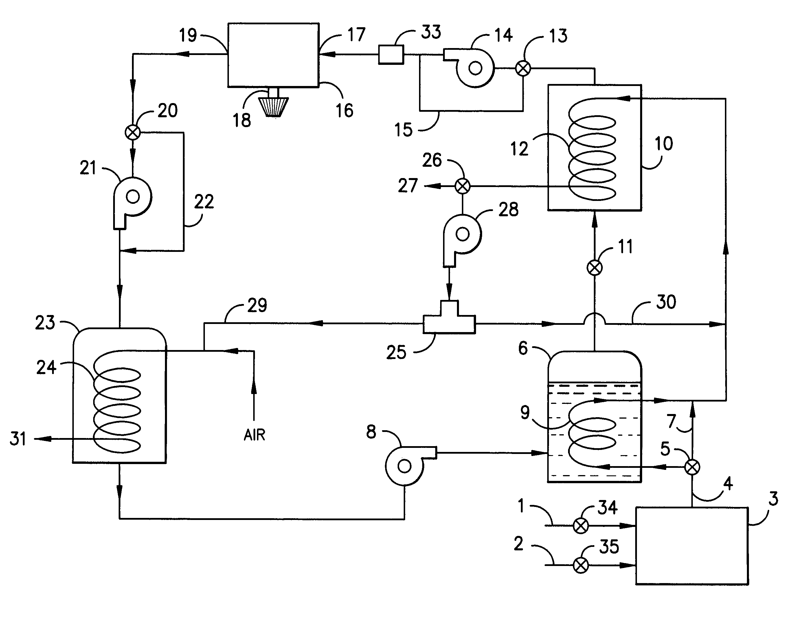
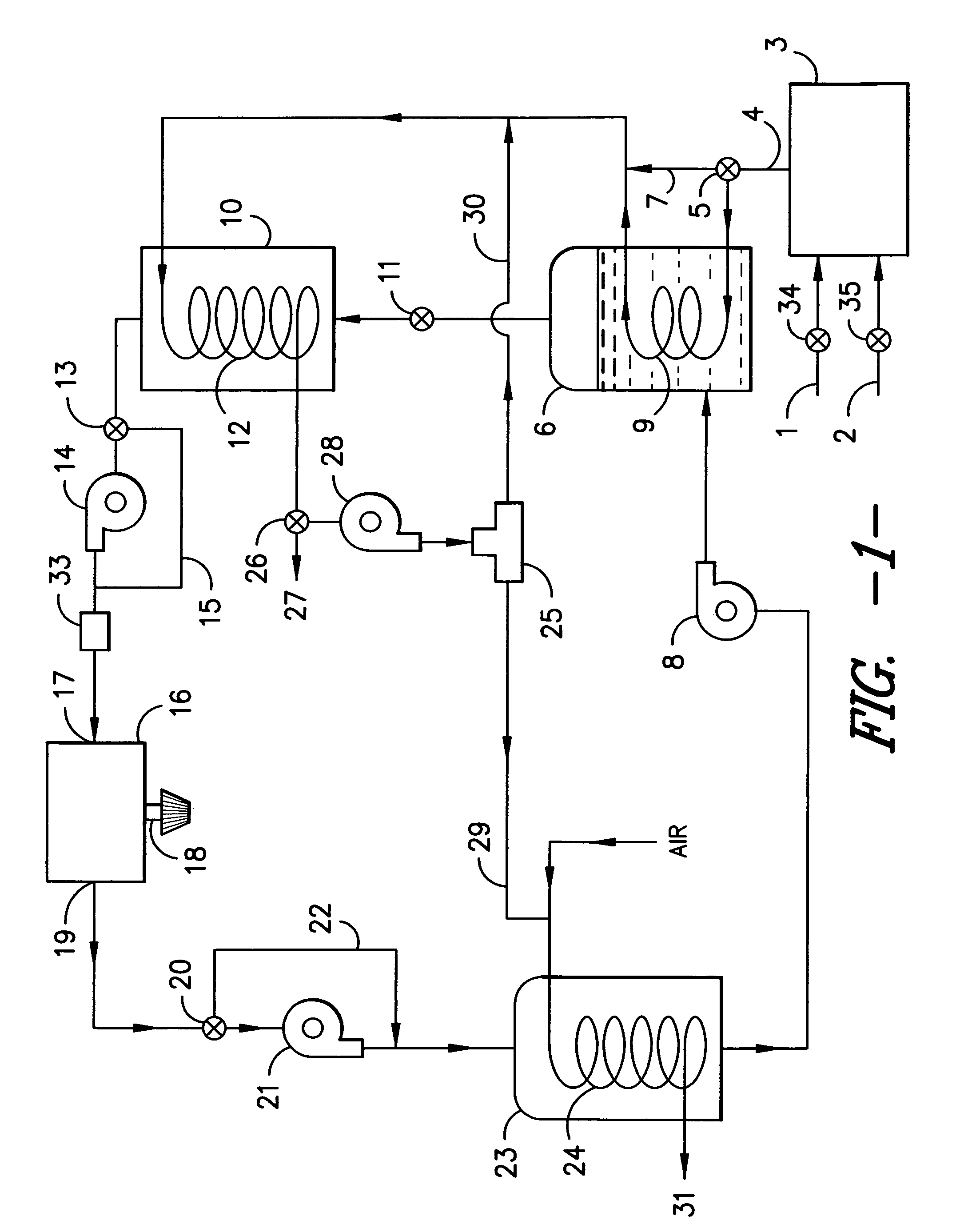
[0042]Referring to FIG. 1, fuel stream 1 and air stream 2 are fed to burner 3 to produce combustion gas stream 4. Valve 5 controls the flow of the combustion gases, which may be diverted all or partially to boiler 6 or bypass 7. Working fluid (liquid state) is fed by pump 8 to boiler 6, where it is heated by the combustion gases. The combustion gases circulate through the heat exchange equipment in boiler 6, shown as coils 9, before passing on to reservoir 10. Any of the combustion gases passing through bypass 7 pass on to reservoir 10. When the engine is first started-up, bypass valve 5 opens to divert a substantial portion of the combustion gases directly to reservoir 10, thereby rapidly heating the working fluid contained therein. In an alternative embodimen...


PUM


Abstract

An organic Rankine engine used to power a vehicle is provided with a quick-start system of pumps, electric heaters or pistons to generate a pressure differential across the motor, prior to the engine reaching operating conditions.

Description

BACKGROUND OF THE INVENTION[0001]This invention relates to an improvement in an external combustion engine, suitable for use in vehicles. The engine employs an organic Rankine cycle.[0002]Steam cars represent one of the earliest applications of external combustion engines to motor vehicles. The Stanley brothers, Francis E. Stanley and Freelan O. Stanley, pioneered the commercialization of steam cars in the United States. In 1906, a steam powered vehicle constructed by the Stanley Steam Motors Corporation set a world speed record of 127.66 mph. Another innovator in the field of external combustion engine powered vehicles was Abner Doble. His improvements to steam power plants may be found in U.S. Pat. No. 1,675,600; U.S. Pat. No. 2,379,887; U.S. Pat. No. 2,393,313; and U.S. Pat. No. 2,440,328. The external combustion engine was eclipsed, however, by the widespread adoption of the internal combustion engine.[0003]Nevertheless, work has continued over the years to develop the external ...

Claims


Application Information

Patent Timeline
Patent Type & Authority Patents(United States)
IPC IPC(8): F01K25/08
CPCF01K13/02F01K15/02F01K25/08
Inventor ROBERTS, JOHN HAMLIN
Owner ROBERTS JOHN HAMLIN
Learn More