Electronic clinical thermometer and operation control method

a technology of operation control and thermometer, which is applied in the field of electronic clinical thermometer, can solve problems such as errors, and achieve the effect of high measurement accuracy

Inactive Publication Date: 2011-04-28
TERUMO KK
View PDF6 Cites 14 Cited by
  • Summary
  • Abstract
  • Description
  • Claims
  • Application Information

AI Technical Summary

Benefits of technology

[0013]The present invention can provide an inexpensive long-life electronic clinical thermometer with high measurement accuracy by using a general-purpose LSI and not using any voltage regulator.

Problems solved by technology

The electronic clinical thermometer using the single-input integrating A / D converter, however, has the characteristic that an error occurs due to the influence of changes in the power supply voltage.

Method used


Image

  • Electronic clinical thermometer and operation control method
  • Electronic clinical thermometer and operation control method
  • Electronic clinical thermometer and operation control method

Examples


first embodiment

[0027]

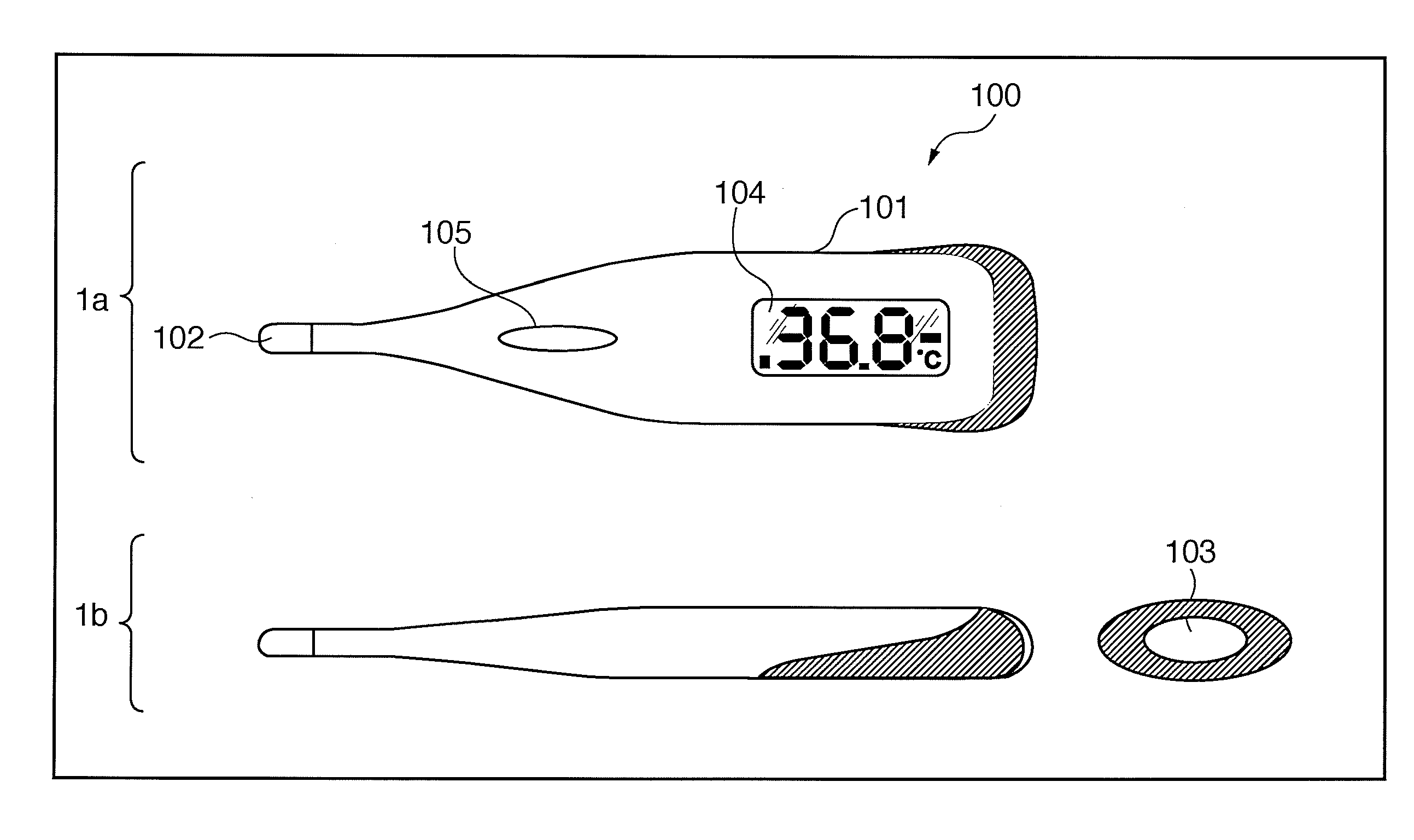
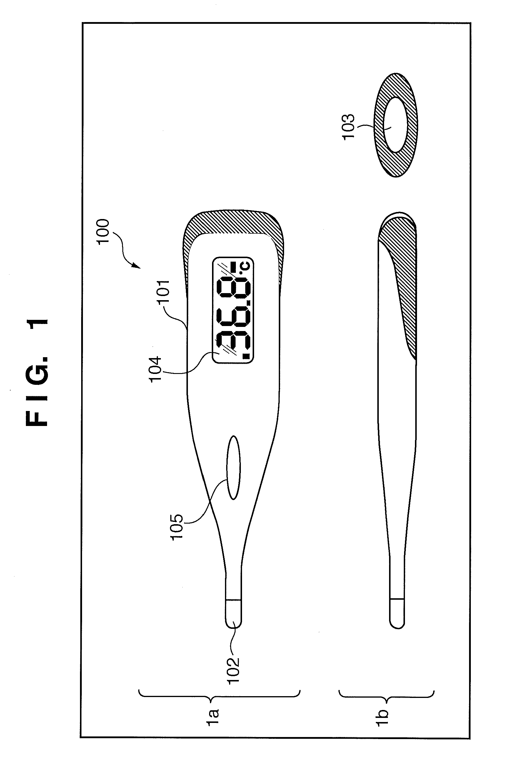
[0028]FIG. 1 is a view showing the outer appearance of an electronic clinical thermometer 100 according to an embodiment of the present invention. 1a of FIG. 1 is a plan view, and 1b of FIG. 1 is a side view. Reference numeral 101 denotes a main body case containing electronic circuits such as an arithmetic controller 220 (to be described later), a battery (power supply) 240, and the like.

[0029]Reference numeral 102 denotes a metal cap made of stainless steel and containing, for example, a thermistor (to be described in detail later) for measuring the temperature. Reference numeral 103 denotes a power ON / OFF switch. The power supply is turned on when the switch 103 is pressed once, and turned off when the switch 103 is pressed again.

[0030]Reference numeral 104 denotes a display unit that displays the body temperature of an object; and 105, a sound output unit that outputs a sound based on processing in the arithmetic controller 220.

[0031]

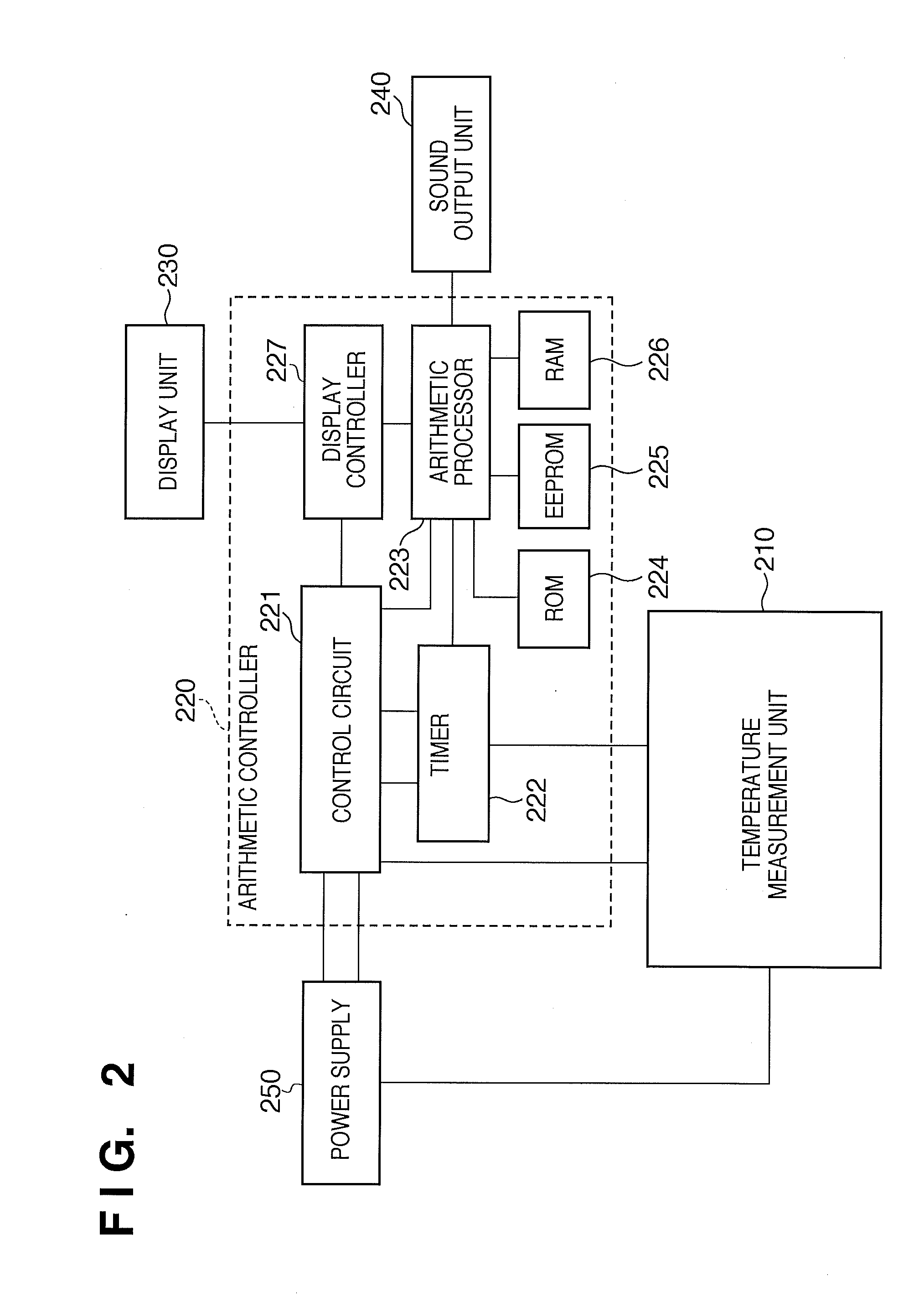
[0032]FIG. 2 is an internal block diagr...

second embodiment

[0104]In the above-mentioned first embodiment, one temperature measurement process is completed by repeating the charge / discharge of the capacitor four times immediately after the temperature measurement process is started. However, the present invention is not limited to this. For example, it is also possible to complete one temperature measurement process by repeating the charge / discharge of the capacitor three times.

[0105]More specifically, it is possible to set the charge sequence such that first time: reference resistance element, second time: reference resistance element, and third time: thermistor, and calculate temperature data by comparing a second discharge time Tref1 with a third discharge time Tth, without using a first discharge time Tref0.

[0106]Alternatively, it is also possible to set the charge sequence such that first time: reference resistance element, second time: thermistor, and third time: reference resistance element, and calculate temperature data by using the...

third embodiment

[0107]In the above-mentioned first embodiment, one temperature measurement process is completed by repeating the charge / discharge of the capacitor four times immediately after the temperature measurement process is started. However, the present invention is not limited to this. For example, it is also possible to complete one temperature measurement process by repeating the charge / discharge of the capacitor after the voltage drop of the power supply caused by the repetitive measurement of the discharge time has converged within the range of a predetermined threshold value.

[0108]FIG. 9 is a flowchart showing the procedure of a temperature measurement process according to this embodiment. FIG. 10 is a graph showing the change in voltage across a capacitor 403 with time, and the change in output digital signal from an A / D converter 420 with time. The procedure of the temperature measurement process according to this embodiment will be explained below with reference to FIGS. 9 and 10.

[0...


PUM

PropertyMeasurementUnit
temperatureaaaaaaaaaa
timeaaaaaaaaaa
timeaaaaaaaaaa

Abstract

The electronic clinical thermometer includes a thermistor, a reference resistor, a voltage switch for selectively applying a voltage in order to accumulate electric charge in a capacitor via the thermistor or reference resistor, an A / D converter for detecting a voltage change occurring when removing the electric charge accumulated in the capacitor, and outputting an ON signal while the capacitor has a voltage equal to or higher than a predetermined voltage, a timer for measuring the duration of the ON signal, and an arithmetic processor for calculating the ambient temperature of the thermistor by using the discharge time when removing the electric charge accumulated in the capacitor via the thermistor, and the average value of the discharge times when removing the electric charge accumulated in the capacitor via the reference resistor immediately before and after removing the electric charge accumulated in the capacitor via the thermistor.

Description

TECHNICAL FIELD[0001]The present invention relates to an electronic clinical thermometer.BACKGROUND ART[0002]In the field of electronic clinical thermometers, a single-input integrating A / D converter has conventionally been used as a technique for measuring the resistance change of a thermistor caused by a temperature change.[0003]The single-input integrating A / D converter is a circuit capable of accumulating electric charge in an amount proportional to the resistance change of a thermistor when a predetermined power supply voltage is applied, and outputting an ON signal having a duration proportional to the resistance change when the accumulated electric charge is removed. An electronic clinical thermometer can calculate a temperature value by measuring the ON time of the output ON signal from the circuit by using a timer.[0004]The electronic clinical thermometer using the single-input integrating A / D converter, however, has the characteristic that an error occurs due to the influe...

Claims


Application Information

Patent Timeline
Patent Type & Authority Applications(United States)
IPC IPC(8): G01K7/22G01K7/34G06F15/00
CPCG01K7/24G01K2219/00G01K13/002G01K13/20
Inventor SUZUKI, MINORU
Owner TERUMO KK
Why Eureka
Try Eureka