Eureka AIR delivers breakthrough ideas for toughest innovation challenges, trusted by R&D personnel around the world.

Split thermo-electric structure and devices and systems that utilize said structure

Inactive Publication Date: 2011-05-05
LAMOS
View PDF13 Cites 9 Cited by
  • Summary
  • Abstract
  • Description
  • Claims
  • Application Information

AI Technical Summary

Benefits of technology

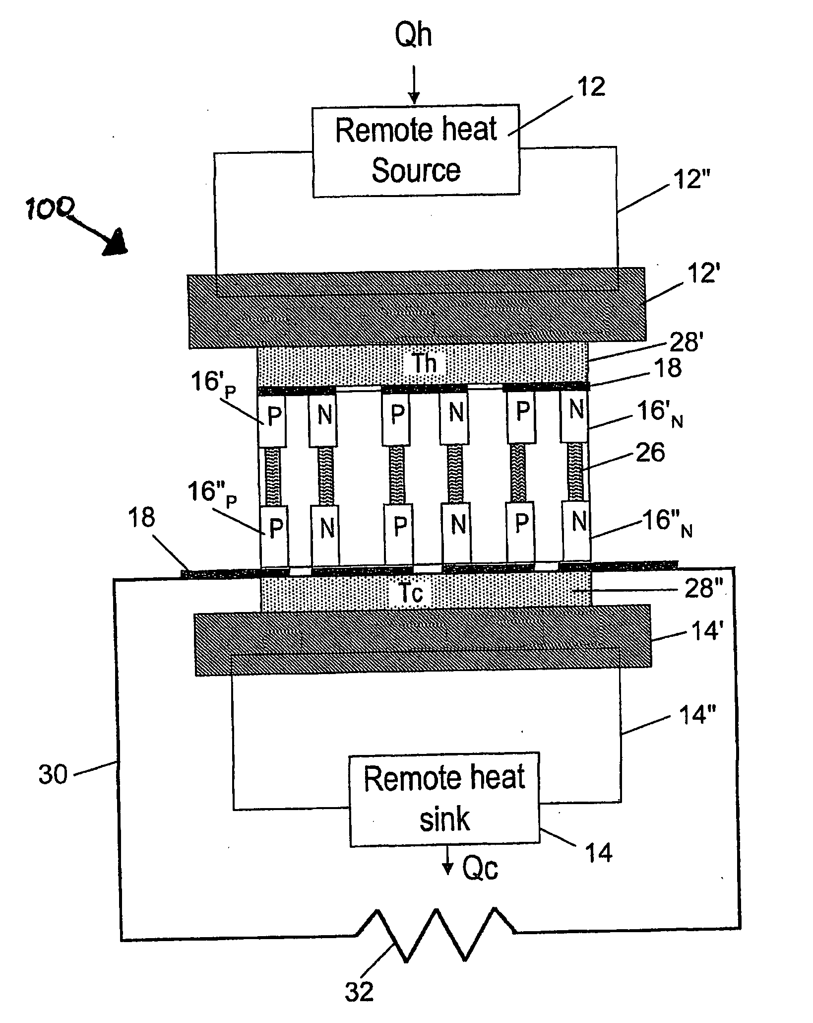
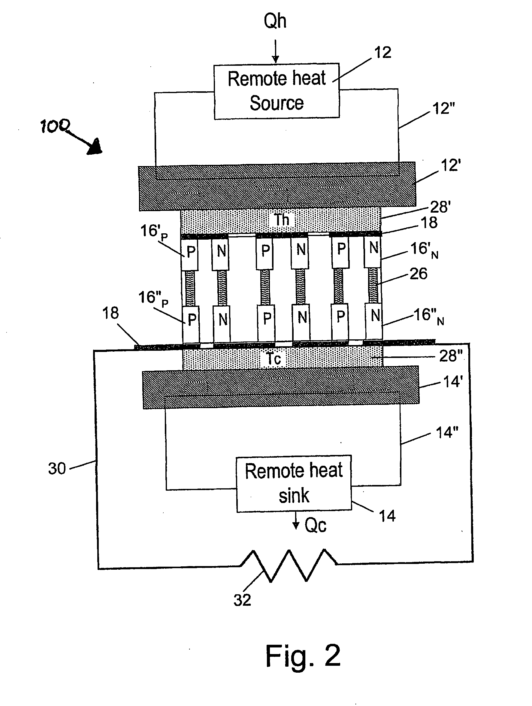
[0027]In a fourth aspect the invention is a system utilizing the thermo-electric device of the third aspect, wherein the first support layer is thermally connected to a heat source and the second support layer is thermally connected to a heat sink. The system of this aspect can be a Seebeck device, wherein the first support layer and the second support layer are maintained at different temperatures such at to generate an electrical current along the STESs that connect them. The system of this aspect can be a Peltier device, wherein a current is caused to flow through the STESs that connect the first support layer and the second support layer, thereby to cool the first support layer and heat the second support layer. In embodiments of this aspect of the invention either the heat source or the heat sink or both are located at a distance from their respective support layer.

Problems solved by technology

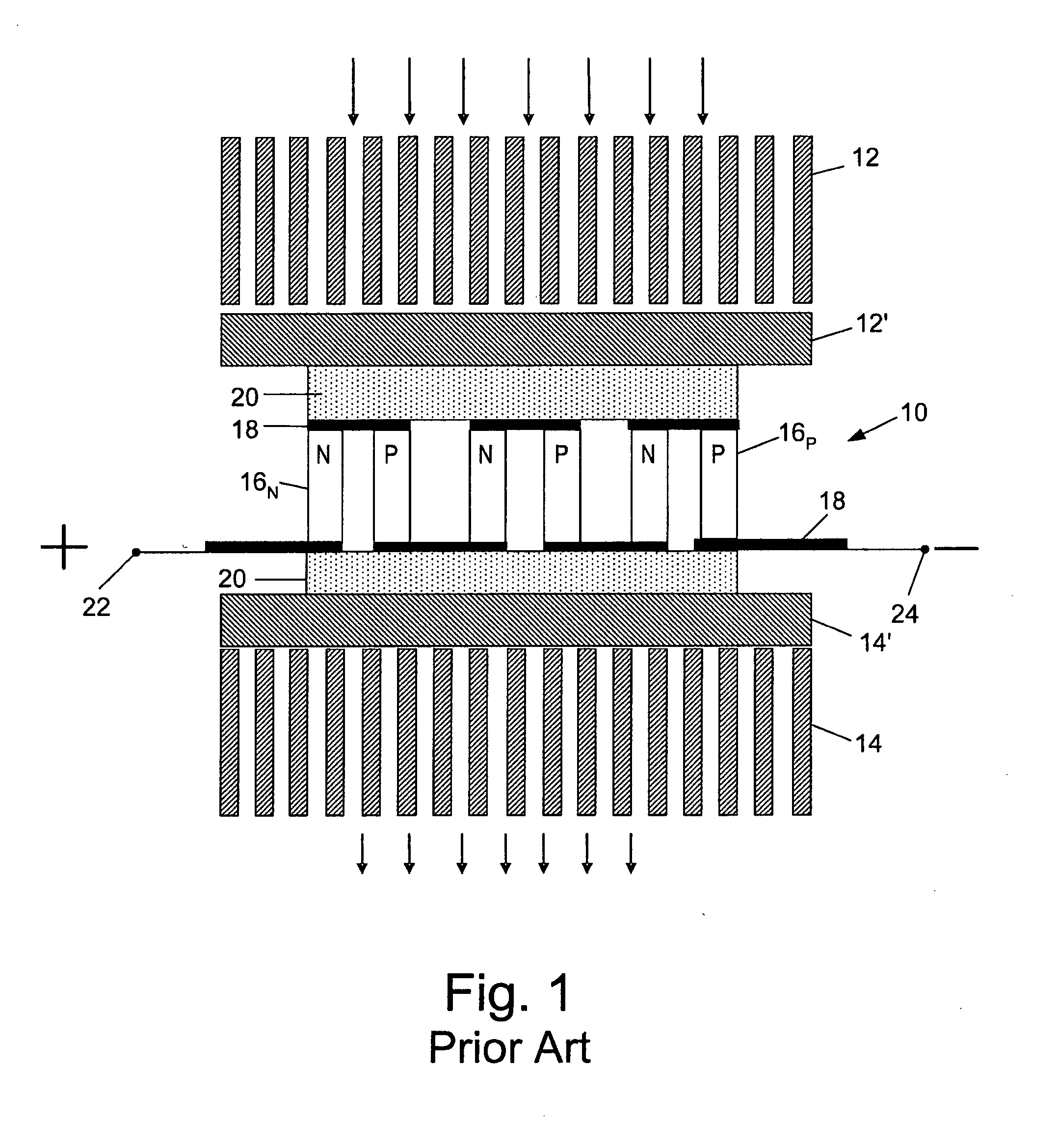
The structure of existing conventional thermo-electric modules puts unavoidable limitations on the magnitude of the heat flux that can be transferred between the heat absorbing and heat dissipating sides of the module.
To accomplish this task complicated large finned heat exchangers are almost always necessary.
However, there are various mechanical constraints which complicate or totally prevent successful thermal coupling of the thermo-electric module to the cold and heat sinks.
The first of these constraints is the shape of the standard module, which means that it can only be coupled to heat sinks having a very specific geometry.
However, this makes the difficulties described above (in paragraph (a) more and more difficult to overcome.
Improper metallization of the ceramics, for instance, or improper soldering or improper nickel-plating are only a few of the potential problems which put in question the survivability and reliability of the thermo-electric module.
In fact, the biggest challenge facing the manufacturer of an optimal thermo-electric module is to maintain an essentially even flatness and compression across all the module elements.
Clearly, the presently available standard thermo-electric modules make it impossible to use available by-product waste heat because the parameters, e.g. dimensions, shape, and location, of the heat source are not compatible with the structure of the thermo-electric modules.
For example, the close vicinity between the “hot” and “cold” faces may not allow the use of available sources of heat or the use of cold zones such as: waste heat or rejected heat, exhaust gas in pipes or from vehicles, heat lost from hot engines, utilization of solar energy, heat dissipation from moving bodies, etc.

Method used


Image

  • Split thermo-electric structure and devices and systems that utilize said structure
  • Split thermo-electric structure and devices and systems that utilize said structure
  • Split thermo-electric structure and devices and systems that utilize said structure

Examples


example 1

[0052]Three split thermo-electric structures similar to that shown in FIG. 4A are constructed wherein L1=L3=1 mm and L2=40 mm for all three structures. The boundary conditions are T1=40 degC and T4=70 degC for all structures. The cross-sectional areas of the elements and internal interface temperatures are as shown in Table 1. The temperatures at the interfaces between elements of the thermo-electric structures of this example are shown in FIG. 5A.

TABLE 1StructureA1A2A3T1T2T3T419794084697029716408266703167940685570

example 2

[0053]Four split thermo-electric structures similar to that shown in FIG. 4A are constructed wherein L1=L3=1 mm and L2=40 mm for all four structures. A1=9 mm2, A2=7 mm2, and A3=16 mm2 for all four structures. The boundary conditions are T1=40 degC and T4=60, 70, 80, and 90 degC for each of the structures respectively. The temperatures at the interfaces between elements of the thermo-electric structures of this example are shown in Table 2 and FIG. 5B.

TABLE 2StructureT1T2T3T4140766060240826670340887380440948090

example 3

[0054]Three split thermo-electric structures similar to that shown in FIG. 4B are constructed wherein A1=25 mm2, A2=7 mm2, A3=25 mm2, A4=7 mm2, and A5=25 mm2 for all three structures. The boundary conditions are T1=45 degC and T6=50 degC for all structures. The lengths of the elements and internal interface temperatures are as shown in Table 3. The temperatures at the interfaces between elements of the thermo-electric structures of this example are shown in FIG. 6A.

TABLE 3StructureL1L2L3L4L5T1T2T3T4T5T6114014014562516147502120160145625767485031601201456146544750


PUM


Abstract

The invention is a Split-Thermo-Electric Structure (STES) and devices and systems that utilize said structure. The STES comprises a first thermo-electric element at an elevated temperature and a second thermo-electric element at a low (cold) temperature. The first thermo-electric element and the second thermo-electric element are connected by either an intermediate connection that conducts both electric current and heat or by a thermo-electric chain comprised of one or more thermo-electric elements. Each pair of the thermo-electric elements in the chain are connected by an intermediate connection that conducts both electric current and heat. Each of the thermo-electric elements and each of the intermediate connections in the STES exhibit a temperature-gradient. The STESs can be utilized in Seebeck or Peltier devices. The STESs can be utilized to construct devices comprised a plurality of n-type and p-type pairs of STESs, wherein each of the STESs in the device are connected at each end to a support layer. One of the support layers can be thermally connected to a heat source and the second support layer thermally connected to a heat sink in order to create a thermo-electric system. The heat source or the heat sink or both can be located at a distance from their respective support layer.

Description

FIELD OF THE INVENTION[0001]The present invention relates to a novel thermo-electric technology, based on split thermo-electric structure.BACKGROUND OF THE INVENTION[0002]Thermo-electric systems for cooling or for power generation are of high interest in a wide range of processes and applications. The structure of existing conventional thermo-electric modules puts unavoidable limitations on the magnitude of the heat flux that can be transferred between the heat absorbing and heat dissipating sides of the module.[0003]The physical principles on which thermo-electric effects are based, i.e. the Seebeck Effect and the Peltier Effect, are well-known since 1821 and 1834, respectively. The Seebeck Effect relates to an electric current which will flow continuously in a closed circuit composed of two dissimilar metals or conductors as long as the connections between the two materials are maintained at a given temperature gradient. Conversely, the Peltier Effect states that when an electrica...

Claims


Application Information

Patent Timeline
IPC IPC(8): H01L35/28H01L35/32
CPCH01L35/32H10N10/17
Inventor DANENBERG, NOAM
Owner LAMOS
Why Eureka
Eureka Blog
Learn More