Monolithic thin-film thermoelectric device including complementary thermoelectric materials

a thermoelectric device and complementary technology, applied in the field of thermoelectric devices, can solve the problems of limited cooling capacity, adversely affecting the performance of these devices, and high hardware cos

Inactive Publication Date: 2005-07-14
NANOCOOLERS
View PDF99 Cites 60 Cited by
  • Summary
  • Abstract
  • Description
  • Claims
  • Application Information

AI Technical Summary

Benefits of technology

[0016] In some embodiments, the present invention provides a vertical, monolithic, thin-film thermoelectric device. A thermoelectric device consistent with the present invention may include thermoelectric elements of opposing conductivity types coupled electrically in series and thermally in parallel by associated electrodes on a single substrate, reducing the need for solder joints or other structures or mechanisms to attach multiple substrates, components, or assemblies together. In operation, a vertical thermoelectric device consistent with the present invention includes contacts on the front side having a temperature (e.g., THOT) substantially different from a temperature (e.g., TCOLD) of a contact thermally coupled to the backside of the substrate. The invention is also contemplated to provide methods for forming and utilizing such structures.

Problems solved by technology

If the heat is not dissipated, it may adversely affect the performance of these devices.
Such passive cooling methods may provide limited cooling capacity due to spatial limitations.
Because of the large required volume, moving mechanical parts, poor reliability and associated cost of the hardware, use of such vapor compression based systems might not be suitable for cooling small electronic devices.
However, unlike conventional vapor compression-based cooling systems, thermoelectric devices have no moving parts.
The lack of moving parts increases reliability and reduces maintenance of thermoelectric cooling devices as compared to conventional cooling systems.
However, typical thermoelectric devices are limited by low efficiency as compared to conventional cooling systems.
However, superlattices are typically grown on semiconductor wafers and then transferred to a metal surface, which may be difficult to achieve.
However, typical manufacturing processes of the cold points require precise lithographic and mechanical alignments.
The tolerances of the manufacturing process for these alignments often result in degraded performance because it is difficult to maintain uniformity in radii and heights of the cold points.
In practice, it may be difficult to achieve nanometer level planarity resulting in point intrusions or absence of contact.
In addition, structured cold point devices achieve only localized cooling in a small area near each cold point.
The small cooling areas result in large thermal parasitics and poor efficiency.

Method used


Image

  • Monolithic thin-film thermoelectric device including complementary thermoelectric materials
  • Monolithic thin-film thermoelectric device including complementary thermoelectric materials
  • Monolithic thin-film thermoelectric device including complementary thermoelectric materials

Examples


Embodiment Construction

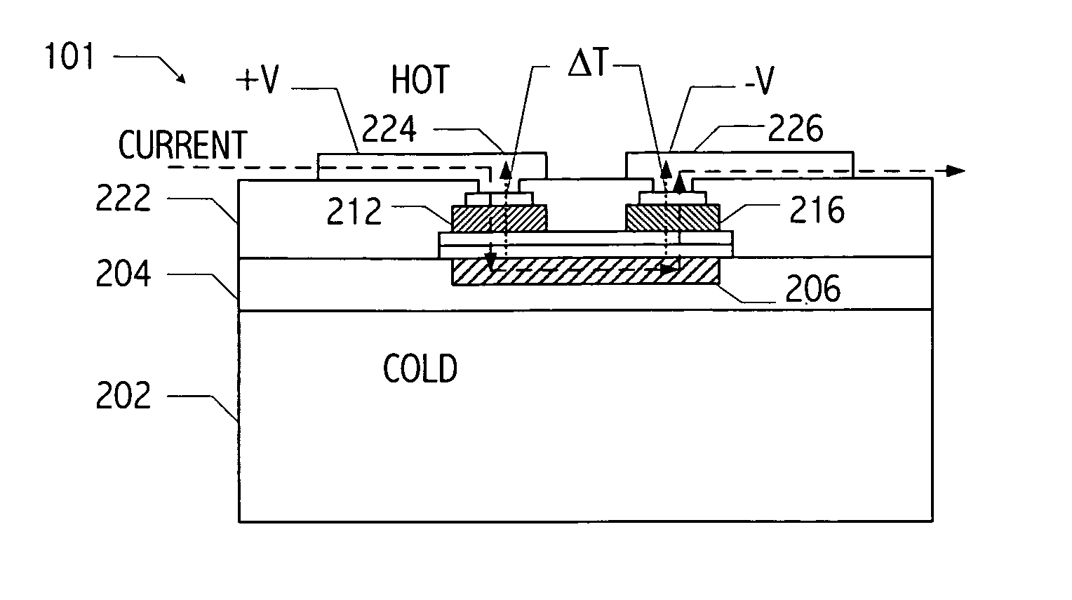
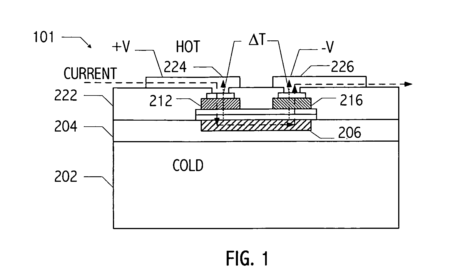
[0051] An exemplary thermoelectric device (thermoelectric device 101 of FIG. 1) includes contacts on a front side (i.e., “top” side) of the structure (e.g., contacts 224 and 226) and a contact thermally coupled to a backside of the structure (e.g. contact 206). As used herein, a contact thermally “coupled” to a backside of the structure may be directly or indirectly coupled to the backside of the structure. In operation, the contacts on the front side of the thermoelectric device have a temperature (e.g., THOT) substantially different from a temperature (e.g., TCOLD) of the contact thermally coupled to the backside of the substrate. The vertical thermoelectric device includes an n-type thermoelectric element and a p-type thermoelectric element (e.g., thermoelectric elements 212, and 216) coupled electrically in series and thermally in parallel. For example, in operation of thermoelectric device 101, a voltage differential is applied between contacts 224 and 226 creating a Peltier ef...


PUM


Abstract

A vertical, monolithic, thin-film thermoelectric device is described. Thermoelectric elements of opposing conductivity types may be coupled electrically in series and thermally in parallel by associated electrodes on a single substrate, reducing the need for mechanisms to attach multiple substrates or components. Phonon transport may be separated from electron transport in a thermoelectric element. A thermoelectric element may have a thickness less than an associated thermalization length. An insulating film between an electrode having a first temperature and an electrode having a second temperature may be a low-thermal conductivity material, a low-k, or ultra-low-k dielectric. Phonon thermal conductivity between a thermoelectric element and an electrode may be reduced without a significant reduction in electron thermal conductivity, as compared to other thermoelectric devices. A phonon conduction impeding material may be included in regions coupling an electrode to an associated thermoelectric element (e.g., a liquid metal).

Description

CROSS-REFERENCE TO RELATED APPLICATION(S) [0001] This application claims the benefit under 35 U.S.C. § 119(e) of U.S. Provisional Application No. 60 / 617,513, filed Oct. 8, 2004, entitled “MONOLITHIC THIN-FILM THERMOELECTRIC DEVICE INCLUDING COMPLEMENTARY THERMOELECTRIC MATERIALS” by Srikanth B. Samavedam, et al., which application is hereby incorporated by reference. [0002] This application is a continuation-in-part of co-pending application Ser. No. 10 / 756,603, filed Jan. 13, 2004, entitled “THERMOELECTRIC DEVICES” by Uttam Ghoshal, which application is hereby incorporated by reference. [0003] This application is related to application Ser. No. ______ (Attorney Docket No. 089-0015), filed on even date herewith, entitled “METHOD FOR FORMING A MONOLITHIC THIN-FILM THERMOELECTRIC DEVICE INCLUDING COMPLEMENTARY THERMOELECTRIC MATERIALS” by Tat Ngai, et al.; and application Ser. No. ______ (Attorney Docket 089-0016), filed on even date herewith, entitled “APPARATUS AND METHOD FOR FORMIN...

Claims


Application Information

Patent Timeline
Patent Type & Authority Applications(United States)
IPC IPC(8): H01L23/38H01L35/02H01L35/04H01L35/12H01L35/30H01L35/34H01L37/00
CPCH01L23/38H01L35/30H01L2924/3011H01L2924/0002H01L2924/00H10N19/00H10N10/13H10N10/01H10N10/17H10N10/80H10N10/81H10N10/85H10N10/851
Inventor GHOSHAL, UTTAMSAMAVEDAM, SRIKANTH B.NGAI, TATMINER, ANDREW CARL
Owner NANOCOOLERS
Why Eureka
Try Eureka