Eureka AIR delivers breakthrough ideas for toughest innovation challenges, trusted by R&D personnel around the world.

Thermoelectrics utilizing thermal isolation

a technology of thermal isolation and thermoelectric devices, applied in the manufacture/treatment of thermoelectric devices, domestic cooling devices, lighting and heating apparatus, etc., can solve the problems of large volume of waste fluid, large fan or pump, and low system efficiency to compete, so as to improve the efficiency of thermoelectric devices and improve overall efficiency. , the effect of improving efficiency

Inactive Publication Date: 2005-04-07
GENTHERM INC
View PDF83 Cites 64 Cited by
  • Summary
  • Abstract
  • Description
  • Claims
  • Application Information

AI Technical Summary

Benefits of technology

In general, an improved efficiency thermoelectric device is achieved by subdividing the overall assembly of thermoelectric elements into thermally isolated sub-assemblies. Overall efficiency may be improved by utilizing the thermal isolation, and controlling the positioning and direction of the flow of the material to be cooled or heated through portions of the thermoelectric device. Efficiency may also be improved, by varying ΔT, and physical, thermal and electrical properties of portions of the overall thermoelectric device.
One aspect of the present invention involves a thermoelectric system for use with at least one medium to be cooled or heated. The system has a plurality of thermoelectric elements forming a thermoelectric array with a cooling side and a heating side; wherein the plurality of thermoelectric elements are substantially thermally isolated from each other in at least one direction across the array. At least one heat exchanger is provided on at least one of the cooling and / or the heating sides and in thermal communication with at least one thermoelectric element. The heat exchanger is configured to significantly maintain the thermal isolation of the thermoelectric elements.
Another aspect of the present invention involves a method of making a thermoelectric system for use with at least one medium, such as a fluid, solid or combination of fluid and solid, to be cooled or heated. The method involves the steps of forming a plurality of thermoelectric elements into a thermoelectric array with a cooling side and a heating side; wherein the plurality of thermoelectric elements are substantially thermally isolated from each other in at least one direction across the array, and exchanging heat from at least one side of the thermoelectric array in a manner that significantly maintains the thermal isolation of the thermoelectric elements.

Problems solved by technology

However, usages are limited, because system efficiencies are too low to compete with those of most refrigeration systems employing freon-like fluids (such as those used in refrigerators, car HVAC systems, building HVAC systems, home air conditioners and the like).
However, this has the disadvantage of requiring large fans or pumps and a large volume of waste fluid (that is, fluid not cooled, but exhausted as part of the process to achieve more efficient cooling).
In general, however, these methods are difficult to implement or cost, weight, size or other conditions limit their use.
The result is that ΔT is substantially larger than ΔTc in most devices, and efficiency suffers accordingly.

Method used


Image

  • Thermoelectrics utilizing thermal isolation
  • Thermoelectrics utilizing thermal isolation
  • Thermoelectrics utilizing thermal isolation

Examples


Embodiment Construction

is made in conjunction with the following figures.

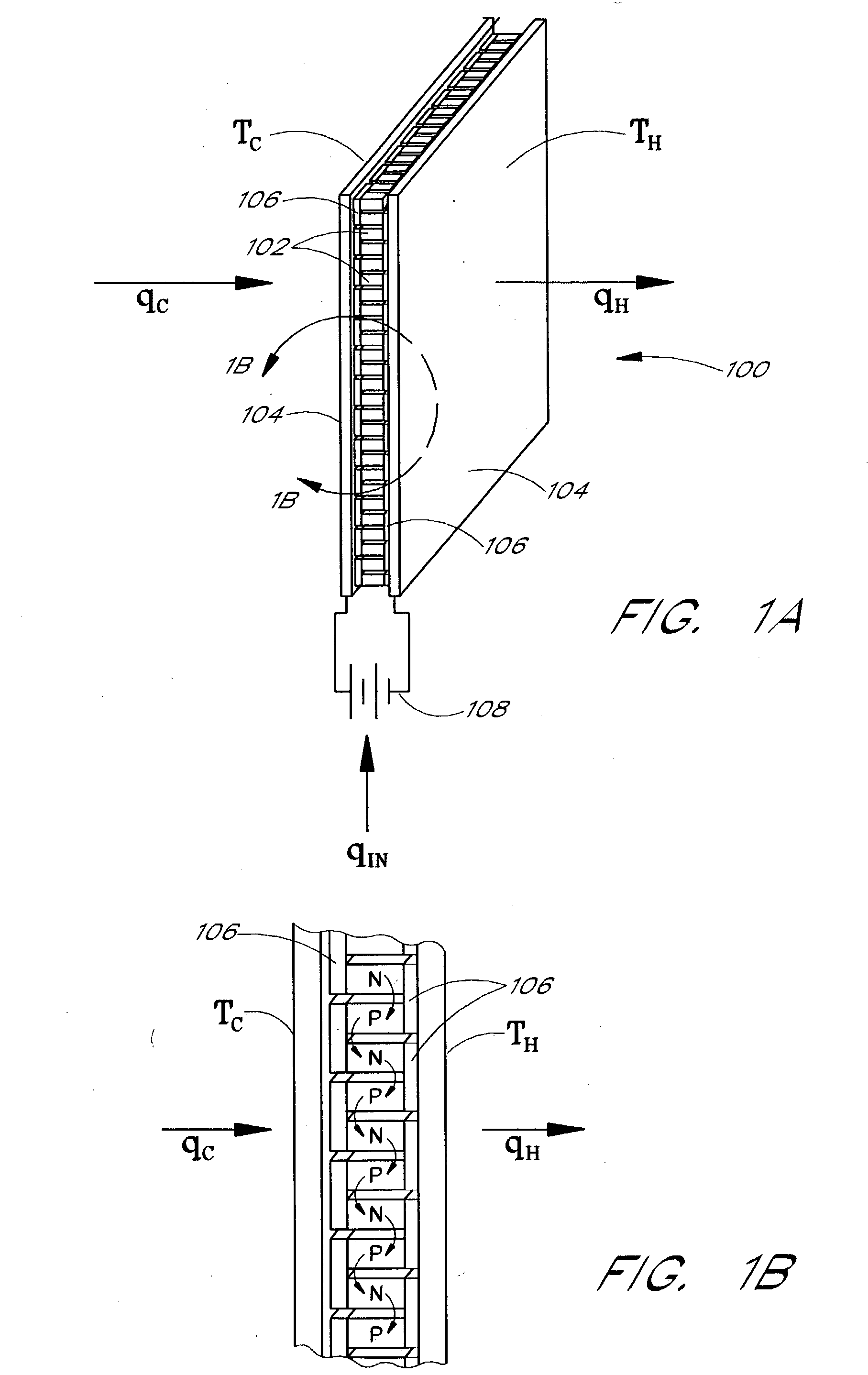
FIGS. 1A and 1B depict a conventional thermoelectric device;

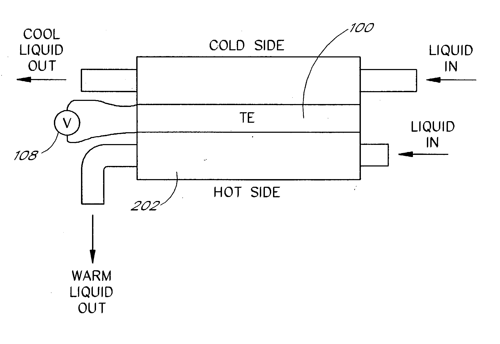
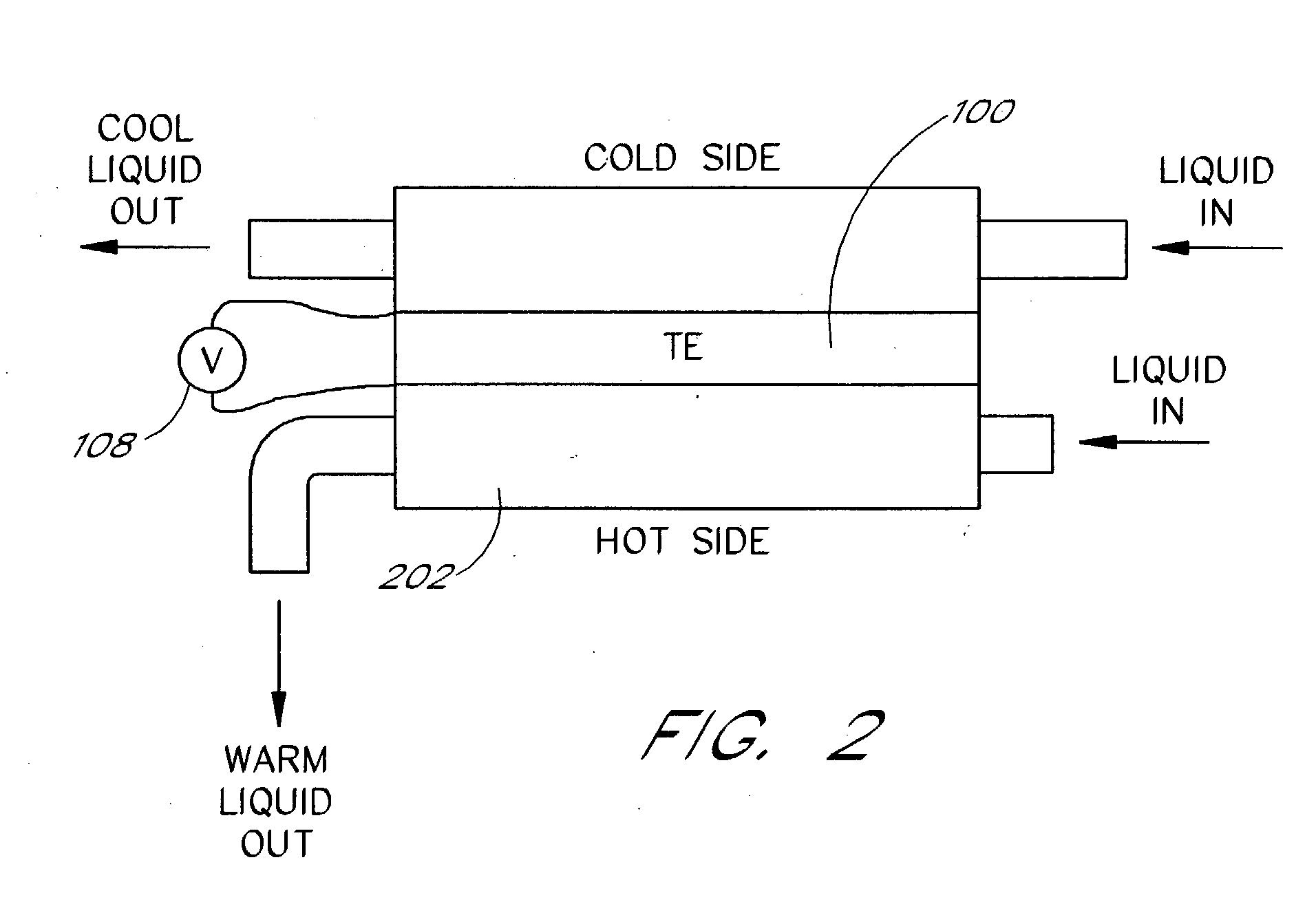
FIG. 2 depicts a conventional thermoelectric device in a conventional fluid heating or cooling application;

FIG. 3 depicts a conventional thermoelectric element for use in cooling a material or component;

FIG. 4 depicts an efficiency measure of various thermoelectric materials;

FIG. 5 illustrates a generalized conditions diagram of conventional thermoelectric devices;

FIG. 6 illustrates a generalized block diagram of a thermoelectric system;

FIG. 7A depicts a first embodiment of a thermoelectric system in accordance with the present invention and its accompanying temperature profiles;

FIGS. 7B and 7C depict a more detailed illustration of the construction of the thermoelectric system of FIG. 7A;

FIGS. 7D and 7E depict alternative embodiments of the thermoelectric system of FIG. 7A, including additional enhancements according to the present invention;

FIG. 8 depicts a thermo...


PUM


Abstract

An improved efficiency thermoelectric system and method of making such a thermoelectric system are disclosed. Significant thermal isolation between thermoelectric elements in at least one direction across a thermoelectric system provides increased efficiency over conventional thermoelectric arrays. Significant thermal isolation is also provided for at least one heat exchanger coupled to the thermoelectric elements. In one embodiment, the properties, such as resistance or current flow, of the thermoelectric elements may also be varied in at least one direction across a thermoelectric array. In addition, the mechanical configuration of the thermoelectric elements may be varied, in one embodiment, according to dynamic adjustment criteria.

Description

BACKGROUND OF THE INVENTION 1. Field of the Invention The present invention relates to improved thermoelectrics for producing heat and / or cold conditions with a greater efficiency. 2. Description of the Related Art Thermoelectric devices (TEs) utilize the properties of certain materials to develop a thermal gradient across the material in the presence of current flow. Conventional thermoelectric devices utilize P-type and N-type semiconductors as the thermoelectric material within the device. These are physically and electrically configured in such a manner that the desired function of heating or cooling. Some fundamental equations, theories, studies, test methods and data related to TEs for cooling and heating are described in H. J. Goldsmid, Electronic Refrigeration, Pion Ltd., 207 Brondesbury Park, London, NW2 5JN, England (1986). The most common configuration used in thermoelectric devices today is illustrated in FIG. 1. Generally, P-type and N-type thermoelectric elements ...

Claims


Application Information

Patent Timeline
Patent Type & Authority Applications(United States)
IPC IPC(8): F02G1/043F25B21/02F24H1/18F25B21/04F25B33/00H01L23/427H01L35/00H01L35/30H01L35/32H01L35/34H02N11/00
CPCF02G1/043F25B21/02F25B21/04F25B33/00F25B2321/021F25B2500/01H01L2924/0002H01L35/00H01L35/30H01L35/32H01L2924/00F28D15/0275H10N10/00H10N10/13H10N10/17
Inventor BELL, LON E.
Owner GENTHERM INC
Why Eureka
Eureka Blog
Learn More