Adhesive Label, Adhesive Label Roll, Photosensitive Web Unit, and Apparatus for and Method of Manufacturing Photosensitive Laminated Body

a technology of adhesive labels and laminated bodies, applied in the direction of manufacturing tools, identification means, instruments, etc., can solve the problems of complex structure of the above-ground apparatus for performing the conventional film application process, and affecting the quality of the finished product. , to achieve the effect of simple structure, convenient handling and reliable and efficient peeling

Inactive Publication Date: 2011-05-05
FUJIFILM CORP
View PDF2 Cites 3 Cited by
  • Summary
  • Abstract
  • Description
  • Claims
  • Application Information

AI Technical Summary

Benefits of technology

[0014]It is a general object of the present invention to provide an adhesive label, an adhesive label roll, and a photosensitive

Problems solved by technology

The above apparatus for performing the conventional film applying process is considerably complex in structure because the sticky tape pressing roll 6 and the sticky tape holding base 7 are vertically displaced.
Consequently, a laminated section of a substrate that is positioned downstream of the film applying apparatus is liable to develop a striped defective region.
In addition, the film applying process requires complex and time-consuming maintenance for removing the adhesive material from the sticky tape cutter 5.
Accordingly, the film a

Method used


Image

  • Adhesive Label, Adhesive Label Roll, Photosensitive Web Unit, and Apparatus for and Method of Manufacturing Photosensitive Laminated Body
  • Adhesive Label, Adhesive Label Roll, Photosensitive Web Unit, and Apparatus for and Method of Manufacturing Photosensitive Laminated Body
  • Adhesive Label, Adhesive Label Roll, Photosensitive Web Unit, and Apparatus for and Method of Manufacturing Photosensitive Laminated Body

Examples


first embodiment

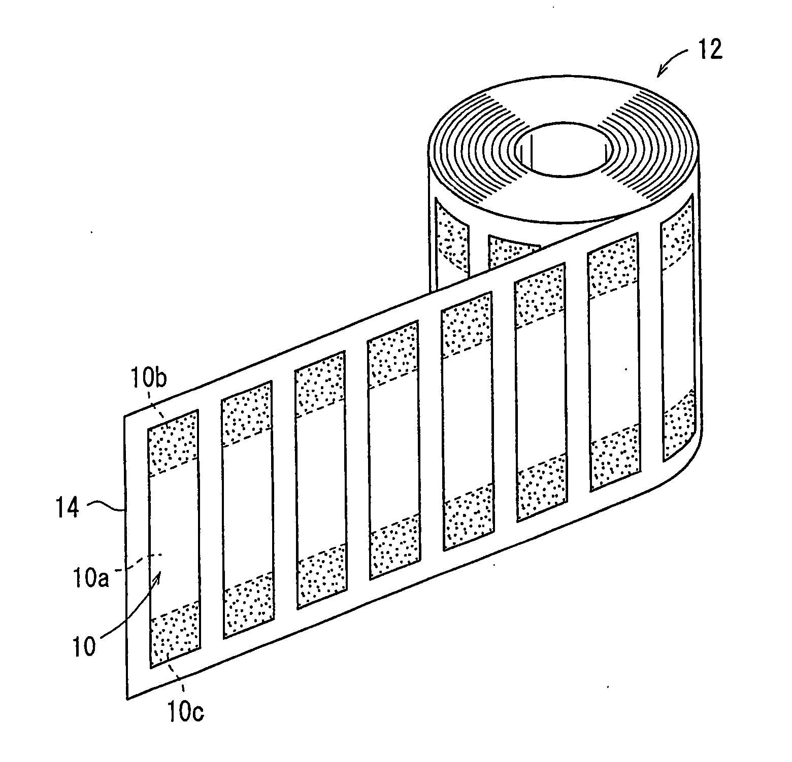
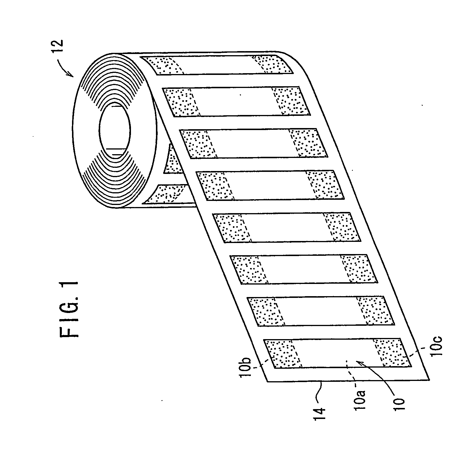
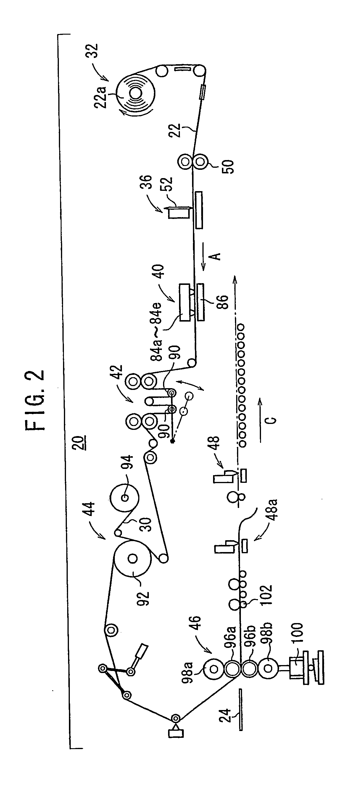
[0048]FIG. 2 schematically shows a manufacturing apparatus 20 according to the present invention, which employs the adhesive label roll 12. The manufacturing apparatus 20 serves to thermally transfer a photosensitive resin layer 28, to be described later on, of an elongate photosensitive web 22 to a glass substrate 24 in a process of producing liquid-crystal panels, color filters or PDPs.

[0049]FIG. 3 shows in cross section a photosensitive web 22 that is employed in the manufacturing apparatus 20. The photosensitive web 22 comprises a laminated assembly of a flexible base film (support) 26, a photosensitive resin layer (photosensitive material layer) 28 disposed on the flexible base film 26, and a protective film 30 disposed on the photosensitive resin layer 28. For example, the protective film 30 is made of polypropylene and has a thickness of 15 μm.

[0050]As shown in FIG. 2, the manufacturing apparatus 20 comprises a web reel-out mechanism 32 for accommodating a photosensitive web ...

second embodiment

[0097] since the photosensitive web unit 124 is employed, the peeling mechanism is only required to wind the protective film 30 and hence is relatively simple in structure. Since the partly cutting device (processing mechanism) that tends to emit dust particles and tends to suffer failures is positioned separately from the peeling mechanism, a higher level of cleanness is maintained in the peeling mechanism for stabilized production. As the photosensitive web unit 124 is employed, an apparatus having the peeling mechanism and the joining mechanism may be essentially sufficient to produce substrates for use liquid-crystal panels, printed wiring boards, or PDPs economically.


PUM

PropertyMeasurementUnit
Forceaaaaaaaaaa
Adhesion strengthaaaaaaaaaa
Solubility (mass)aaaaaaaaaa

Abstract

A plurality of adhesive labels (10), each of a rectangular strip shape, are applied at predetermined spaced intervals to a peel-off sheet (14) of paper, which is then rolled into an adhesive label roll (12). Each of the adhesive labels (10) has a non-adhesion area (10a) centrally on a reverse side thereof facing the peel-off sheet (14), the non-adhesion area (10a) having no or weak adhesion force, and a first adhesion area (10b) and a second adhesion area (10c) which are disposed respectively on both sides of the non-adhesion area (10a).

Description

TECHNICAL FIELD[0001]The present invention relates to an adhesive label for being bonded to a film having an alternate array of peel-off and residual sections to join the peel-off sections, an adhesive label roll having such adhesive labels, a photosensitive web unit having an elongate photosensitive web which comprises a photosensitive material layer and protective film that are successively laminated on a support, the protective film including predetermined lengths to be peeled off to expose areas of the photosensitive material layer for being bonded to a substrate, and an apparatus for and a method of manufacturing a photosensitive laminated body from the elongate photosensitive web.BACKGROUND ART[0002]Substrates for use in liquid-crystal panels, printed wiring boards, and PDPs (plasma display panels) have a photosensitive sheet (photosensitive web) having a photosensitive material layer (photosensitive resin layer) applied to the surface of the substrate. The photosensitive shee...

Claims


Application Information

Patent Timeline
IPC IPC(8): B32B7/14B32B38/18G09F3/10G09F3/00
CPCY10T428/149G09F3/10
Inventor SUEHARA, KAZUYOSHISUZUKI, CHIAKIAKIYOSHI, NOBUYASU
Owner FUJIFILM CORP
Why Eureka
Try Eureka