Advanced SNM Detector

Inactive Publication Date: 2011-05-05
INBAR DAN
View PDF43 Cites 21 Cited by
  • Summary
  • Abstract
  • Description
  • Claims
  • Application Information

AI Technical Summary

Benefits of technology

[0046]Another aspect of this advantage is that compared to the ASP requirement to move the vehicle at 5 MPH, we can theoretically move the vehicle at 5×40=200 MPH and get the ASP number of detected particles. In practice the length of the detector allows screening at highway speeds of 60 MPH while getting close to twice the detectability of an ASP at 5 MPH. Thus, it is possible to get, at highway speed, a higher detectability then that specified for ASP at only 5 MPH. An aspect of some embodiments of the invention is concerned with a non-imaging and/or imaging detector that can detect both gamma rays and neutrons and provide spectral and/or spatial imaging of the radiation of at least one of the kinds. Optionally, both kinds are screened. This allows for the use of a single detector for sensing a wide range of threat signatures.
[0047]An aspect of some embodiments of the invention is concerned with a detector that can identify the general or gross direction of an incident gamma and/or neutron particle independent of the use of a collimator and/or shielding. In an embodiment of the invention, at least some events that are incident from a direction other than a direction from which they are expected when screening an object, can be rejected. This allows for a decrease in background radiation both from environmental radiation and from radiation emanating from other objects (e.g. nuclear medicine patients outside the field of screening). In addition, it enables the rejection of events that enter from the back, sides, top and bottom of the detector. Rejecting events that do not come from the expected direction can increase the reliable threat detectability of the system many fold.
[0048]An aspect of some embodiments of the invention is concerned with imaging guided spectroscopy. In this process, the imaging capability of the detector is used to detect point sources that could be identified as an RDD or SNM or a case of NORM point source at some limited probability (e.g. three to four standard deviations over the ocean of background). To further identify if the point source is a benign (e.g. NORM) or threat, a spectroscopic iso

Problems solved by technology

Such screening is difficult in practice due, at least in part, to the environment in which it is done.
Firstly, environmental radiation (including terrestrial and atmospheric radiation) of gamma rays and neutrons is substantial.
Additionally, humans undergoing nuclear medicine imaging or radiation treatment using implanted radioactive seeds can emit sizeable amounts of radiation.
These and other “natural” or “benign” sources of radiation: this phenomena coupled with the ability to shield (using a heavy metal like lead to shield gammas and low specific gravity materials to shield neutrons) the SNM and RDD, make simple detection schemes either ineffective in finding nuclear radiological threats or prone to a poor receiver operating characteristic (ROC), for example a large percentage of false positives.
Substantial numbers of false positives produce a large number of screened objects (hereinafter, unless otherwise specified, the term object relates to vehicles, trains, shipping containers, packages, luggage, people, cargo and other items that might contain/carry nuclear/radiological threats) that have to be searched or otherwise vetted manually, making such simple systems practically useless for screening large numbers of objects.
ASP syst

Method used


Image

  • Advanced SNM Detector
  • Advanced SNM Detector
  • Advanced SNM Detector

Examples


Embodiment Construction

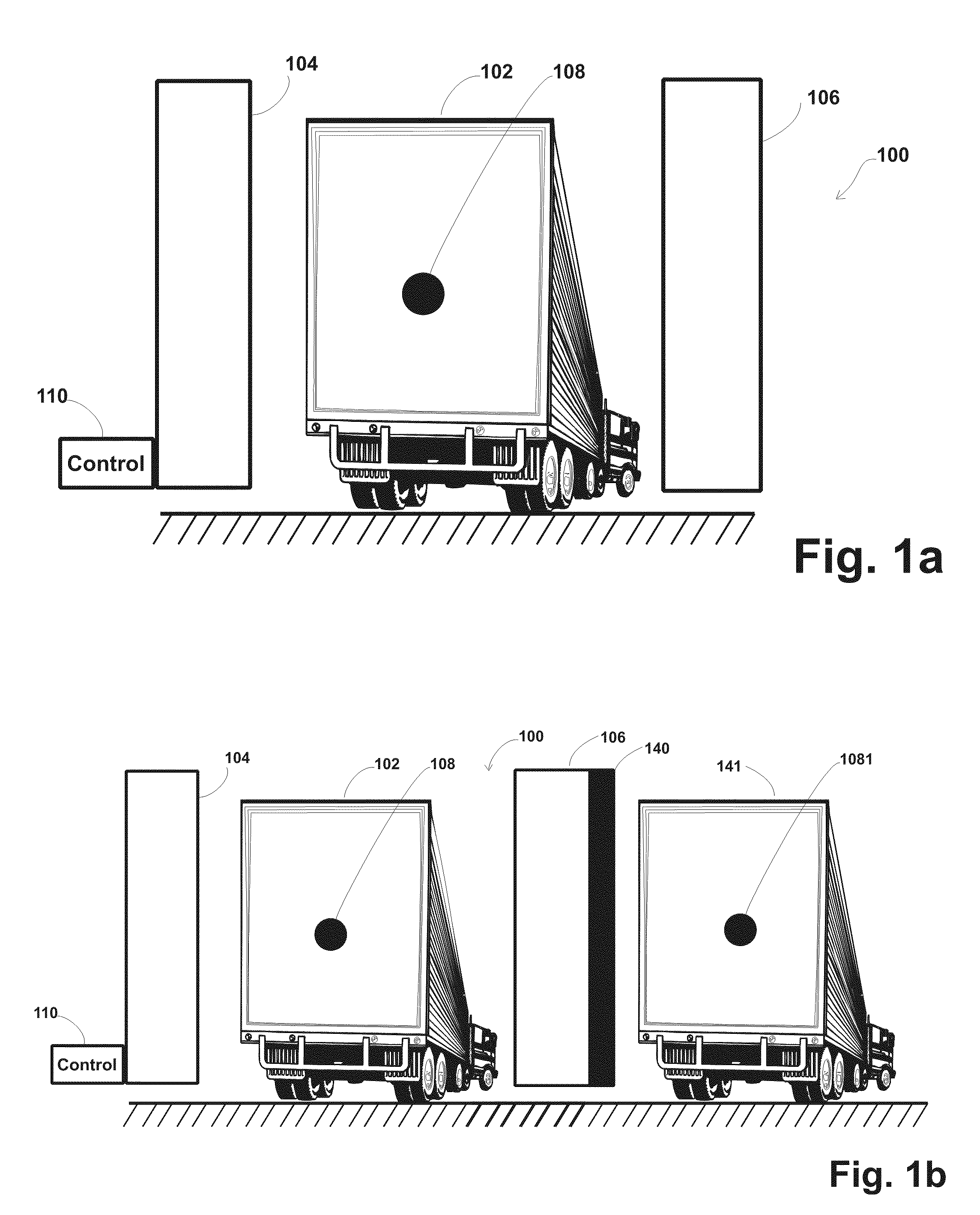
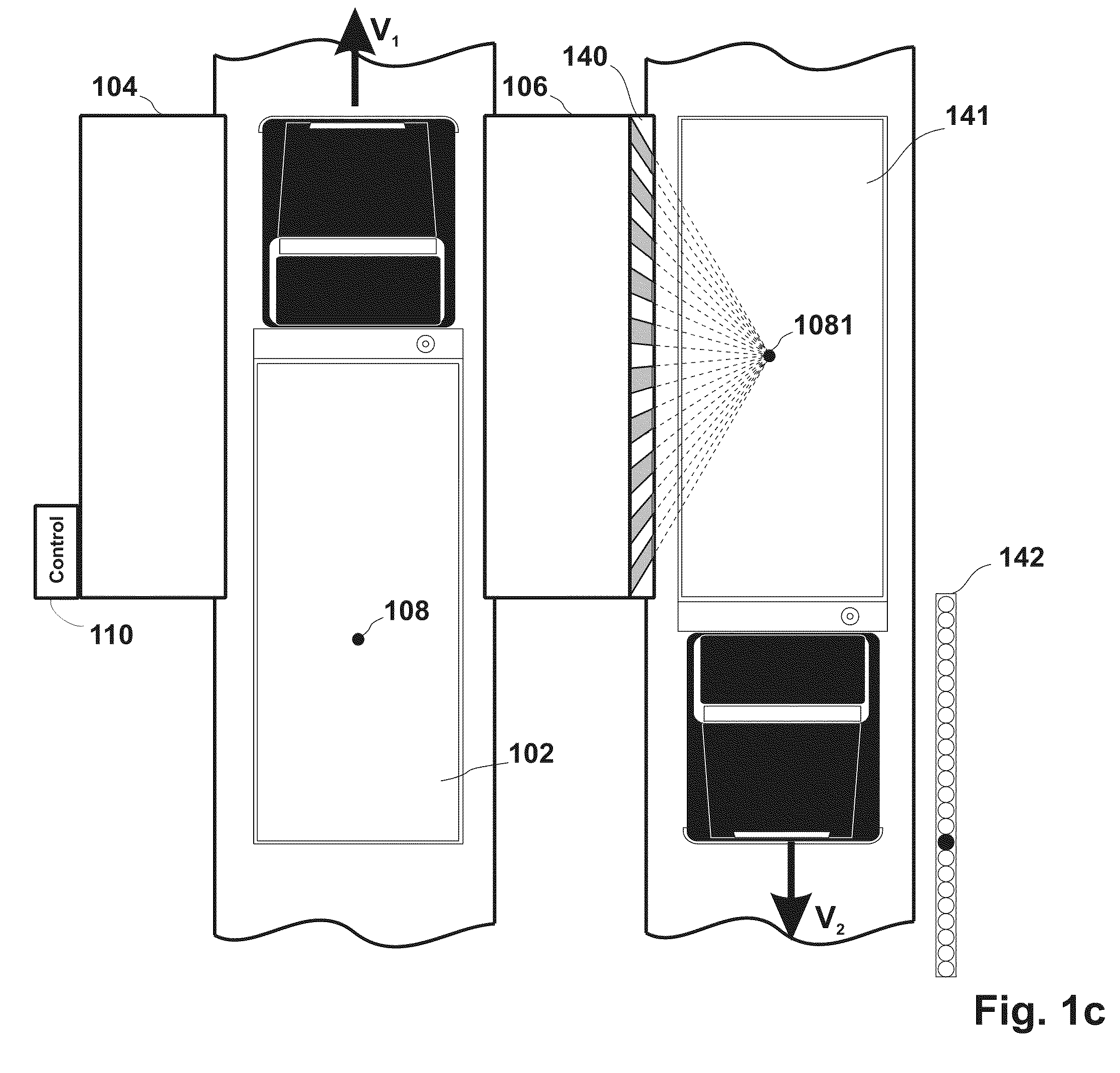
[0203]FIG. 1A shows a schematic drawing of a portion of a system 100 for detecting nuclear threats. As illustrated, vehicles 102, for example a screened object (e.g. a truck,) passes between two detectors 104, 106. In some embodiments only a single detector is used and in some, as described below, two or more such detectors are used. In a preferred embodiment of the invention, the detectors are of one of the types of detectors described below. The detectors are optionally high enough to cover the entire height of the truck or other objects being scanned. The length of the detector (in the direction of motion of the object) is not related to the height; however in some embodiments of the invention it is made 2, 3, 4, 6 or more meters long, so as to provide a desired detection sensitivity.

[0204]For illustration purposes, vehicle 102 is shown carrying a nuclear material 108.

[0205]A controller 110 receives signals from the detectors and based on these signals, and optionally on informat...


PUM


Abstract

A detector for detecting SNM and or RDD radiation. The detector comprising: a plurality of elongated organic scintillator segments arranged in a side by side array; and at least one pair of light sensors optically coupled to ends of each of the scintillator segments such that they receive light from scintillations produced in the scintillator and generate electrical signals responsive thereto.

Description

RELATED APPLICATIONS[0001]The present application is a continuation in part of U.S. patent application Ser. No. 11 / 463,112 filed Aug. 8, 2006 (published Dec. 28, 2006 as US Patent Publication 2006 / 0289775) and claims the benefit under 35 U.S.C. §1.19(e) of U.S. Provisional application, 60 / 767,379 filed Mar. 23, 2006, 60 / 891,551 filed Feb. 26, 2007, 60 / 891,727 filed Feb. 27, 2007, 60 / 891,729 filed Feb. 27, 2007, 60 / 891,738 filed Feb. 27, 2007, 60 / 891,751 filed Feb. 27, 2007, 60 / 892,254 filed Mar. 1, 2007 and 60 / 892,893 filed Mar. 5, 2007. U.S. patent application Ser. No. 11 / 463,112 is a continuation in part of U.S. patent application Ser. No. 11 / 348,040 filed Feb. 6, 2006 (published Dec. 28, 2006 as US Patent Publication 2006 / 0284094) and U.S. patent application Ser. No. 11 / 690,150 filed Mar. 23, 2007 which claims the benefit under 35 U.S.C. §1.19(e) of U.S. Provisional Applications 60 / 649,541 filed Feb. 4, 2005; 60 / 651,622 filed Feb. 11, 2005; 60 / 654,964 filed Feb. 23, 2005. This ap...

Claims


Application Information

Patent Timeline
IPC IPC(8): G01T3/08G01T1/20
CPCG01T1/167G01V5/0091G01T1/20G01T1/2008
Inventor INBAR, DAN
Owner INBAR DAN
Why Eureka
Try Eureka