Vehicle Steering Wheel

a technology for steering wheels and vehicles, applied in the direction of mechanical control devices, pedestrian/occupant safety arrangements, instruments, etc., can solve the problem of relatively laborious installation of wire sections in the steering wheel body, and achieve the effect of simplifying manufacturing

Active Publication Date: 2011-05-05
AUTOLIV DEV AB
View PDF18 Cites 8 Cited by
  • Summary
  • Abstract
  • Description
  • Claims
  • Application Information

AI Technical Summary

Benefits of technology

[0007]Proceeding herefrom, the present invention sets the problem of further ...

Problems solved by technology

A disadvantage, however, is that the installation of the necess...

Method used


Image

  • Vehicle Steering Wheel
  • Vehicle Steering Wheel
  • Vehicle Steering Wheel

Examples


Embodiment Construction

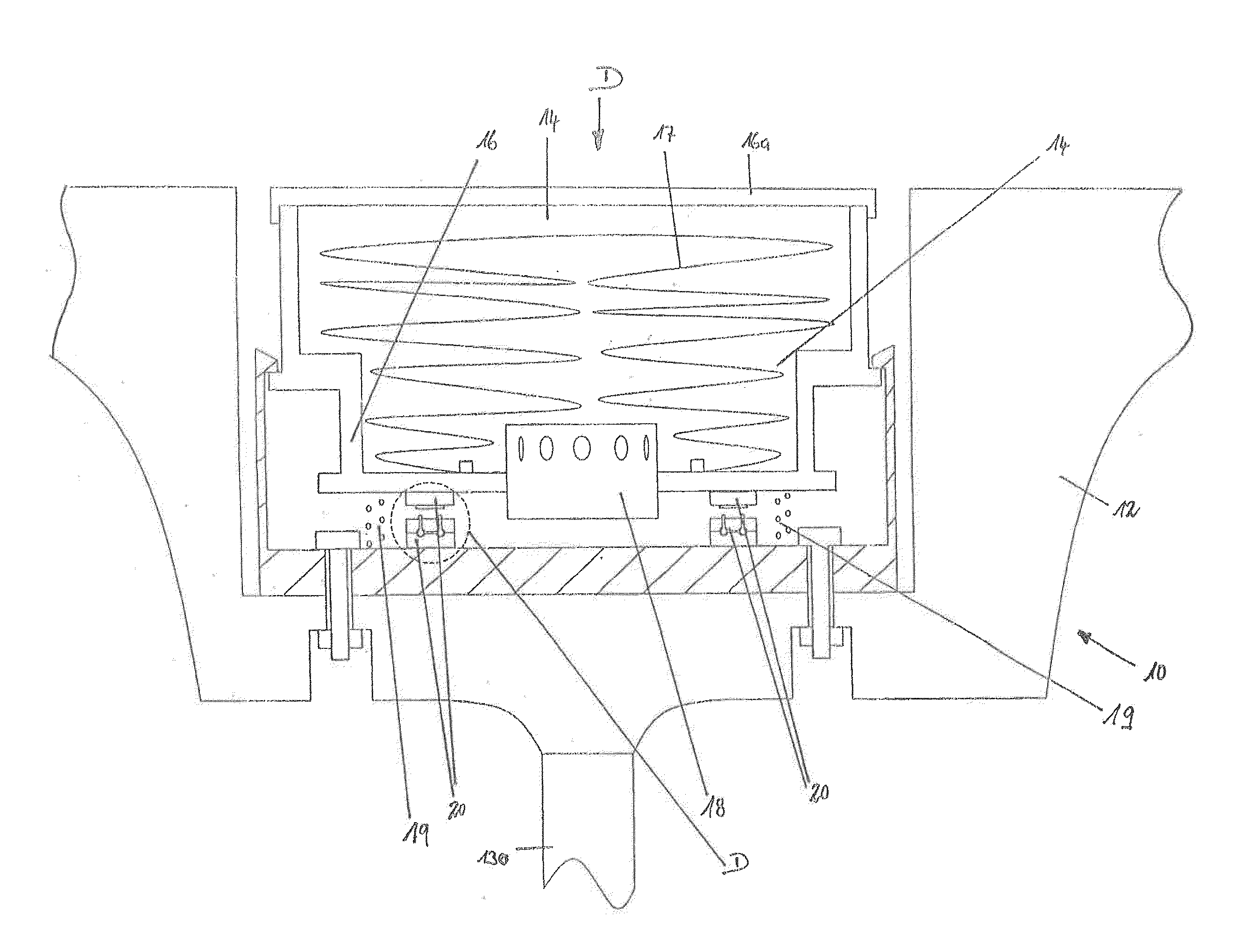
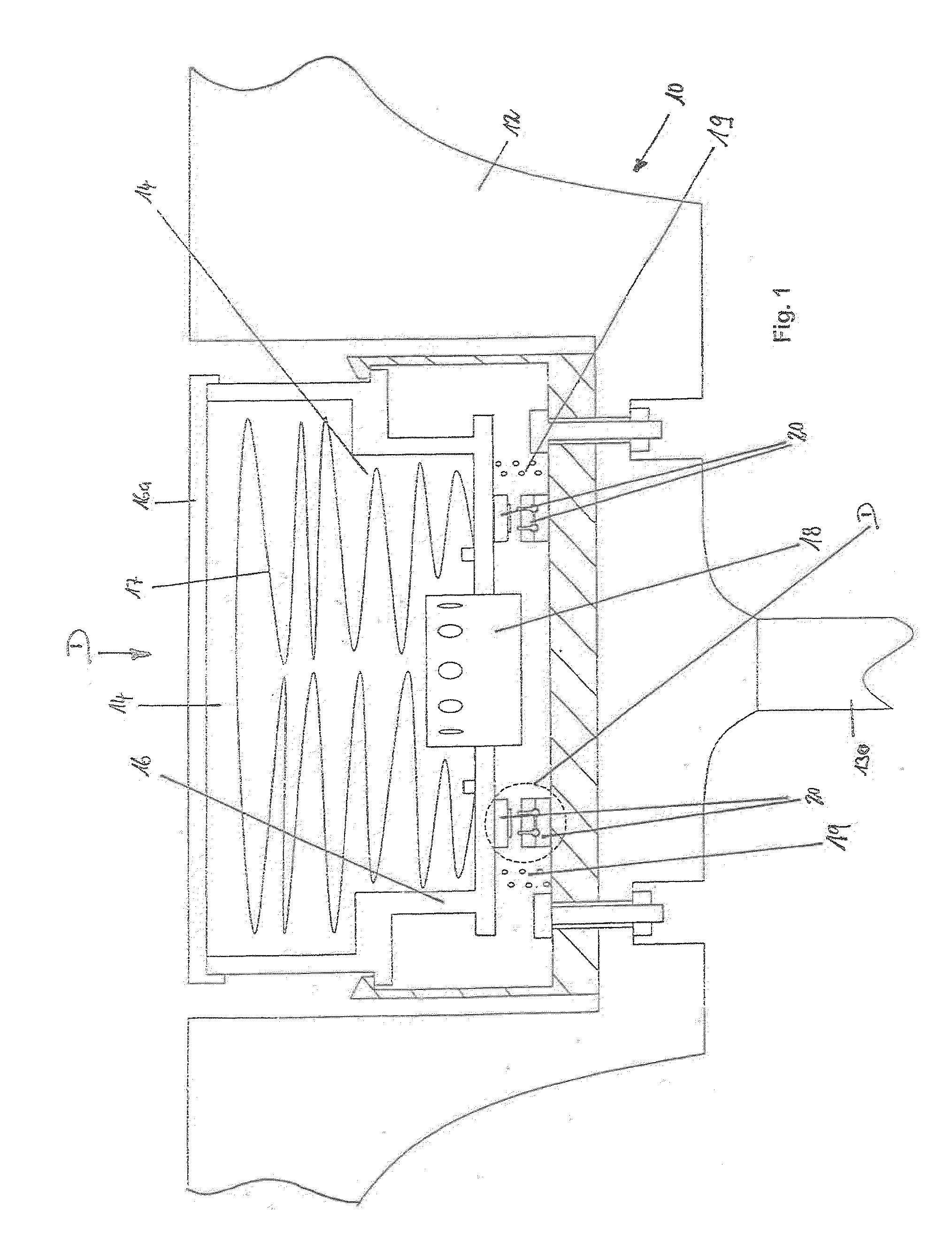
[0027]FIG. 1 shows diagrammatically a cross-section through the hub region of a vehicle steering wheel 10. The vehicle steering wheel 10 has a steering wheel body 12 and an airbag module 14, which is held in a recess of the steering wheel body 12 situated in the hub region. The airbag module 14 is connected with the steering wheel body 12 by means of helical springs 19 which act as return elements. Positioning means are provided, which define the precise position of the airbag module 14 in the steering wheel body 12. The airbag module 14 consists substantially of a housing 16, a airbag 17 folded into the housing 16, a gas generator 18 and a covering element 16a covering the housing, which covering element also constitutes the actuating surface for the horn in the example embodiment which is shown.

[0028]Horn contacts 20 are present, with two horn contacts 20 being illustrated on the basis of the illustration which has been selected; in practice, in most cases three or four horn conta...


PUM


Abstract

A vehicle steering wheel with a steering wheel body, a movable element held movably on the steering wheel body, which element can be pressed down against the force of a restoring element against the steering wheel body, and with a horn contact which is closed by pressing down of the element. An economical design for constructing the horn contact is created in that the horn contact has two cable cores (44a, 44b) which are held in a holding element (32), and that a contact element (36a, 36b) which is likewise held by the holding element (32) extends into each of the cable cores (44a, 44b). The two contact elements (32a, 32b) come into electrical contact with each other here by the pressing down of the movable element.

Description

CROSS REFERENCE TO RELATED APPLICATIONS[0001]This application claims priority to German Patent Application No. 10 2008 029 770.4, filed Jun. 25, 2008 and PCT / EP2009 / 004588, filed Jun. 25, 2009.TECHNICAL FIELD OF THE INVENTION[0002]The invention relates to a vehicle steering wheel for motor vehicles.BACKGROUND OF THE INVENTION[0003]The vehicle steering wheel of almost every motor vehicle has a steering wheel body which is rigidly connected with the steering column, and at least one element which can be pressed down against the force of a return element against the steering wheel body, a horn contact being closed by the pressing down of this element.[0004]In many cases, the movable element which can be pressed down is an airbag module or a part thereof. In the former case, the entire airbag module, i.e. an assembly substantially consisting of a housing, an airbag folded into the housing, a gas generator connected with the housing and a covering element spanning the housing, is held by...

Claims


Application Information

Patent Timeline
IPC IPC(8): B60R21/203B62D1/04
CPCY10T74/20834B60Q5/003
Inventor NEBEL, RAIMUNDMACKENSEN, JURGENADOLPH, OLIVER
Owner AUTOLIV DEV AB
Why Eureka
Try Eureka