Detection of moving objects

a technology for moving objects and position determination, applied in the direction of subscriber station connection selection arrangements, indirect connection, reradiation, etc., can solve the problems of application not disclosing, application not disclosing, etc., and achieve the effect of reducing the size of data and transmitting very large data packages

Inactive Publication Date: 2011-05-05
SMARTER FARMING
View PDF9 Cites 26 Cited by
  • Summary
  • Abstract
  • Description
  • Claims
  • Application Information

AI Technical Summary

Benefits of technology

[0026]The system may advantageously be used for tracking each single movable object. By means of the computer system it may be possible to perform a search for each single piece of cattle, whether in the stable or in the field. On large fields, each single piece of cattle may thus be searched very quickly even in case of cattle located far away from the stable or other service function in connection with the cattle farming. On large open fields it will therefore be a good idea to ensure continuously that each individual piece of cattle at least to a limited extent moves around in order hereby to indicate that the animal is sound and healthy.
[0030]The system may transmit and receive pulses at different time intervals. Hereby may be achieved that e.g. a certain time of the day, e.g. at night, is chosen for transmitting to the individual movable objects at longer time intervals than at the daytime. Correspondingly, by a differentiated time interval it becomes possible to monitor animals which in principle are unstable far more frequently than animals that normally behave very calmly. A standard time interval may be a couple of seconds between each detection, but e.g. at night the intervals may be reduced to e.g. once every 5th minute. For example, it also becomes possible to communicate with calm animals just once in a minute. A system using ultra wideband may in principle communicate several times by each millisecond, but particularly by monitoring cattle monitoring once per second may be more than sufficient, and in practice a less frequent monitoring will possibly be perfectly applicable. By reducing the number of pulses to be transmitted, the battery service life may be increased in the movable objects such that a battery service life far beyond the expected lifetime of a piece of cattle may be attained. A typical battery service life by signal transmission once per second will typically be five years. If the number of signals is substantially reduced, the battery service life may probably be increased; however, since the batteries also are self-discharging, it is doubtful whether the battery service life can be prolonged significantly beyond five years.
[0035]In an alternative embodiment of the invention the short-range radio communications system can communicate in the ultra wideband frequency spectrum, which communication can be performed in a protocol for coding the data which has to be transmitted. Short-range radio communication can also be performed in the ultra wideband frequency spectrum. In this ultra wideband frequency spectrum, it is possible to transmit very large data packages. By ultra wideband communication, it is possible to communicate with each individual animal. In this way, it is possible for the computer system carried by the animal to be in touch with the central processor immediately. In fact, the central computer system could be in touch with each animal even in a large farm where hundreds of animals are placed in a stable or in a field, each computer system carried by the animals can communicate several times per minutes. By using ultra wideband frequency spectrum communication, it is also possible to use received signals from animals for position detection of an animal. The ultra wideband communication makes it possible to position the animals one by one, and then perform a registration of the position of the animal. A further description of position detection of animals is described in the non-published Danish patent application PA 2008 00638 filed by the same applicant.

Problems solved by technology

On the other hand, this patent application does not disclose any kind of position determination of the cattle.
The patent application does not disclose any position indication of the cattle.

Method used


Image

  • Detection of moving objects
  • Detection of moving objects
  • Detection of moving objects

Examples


Embodiment Construction

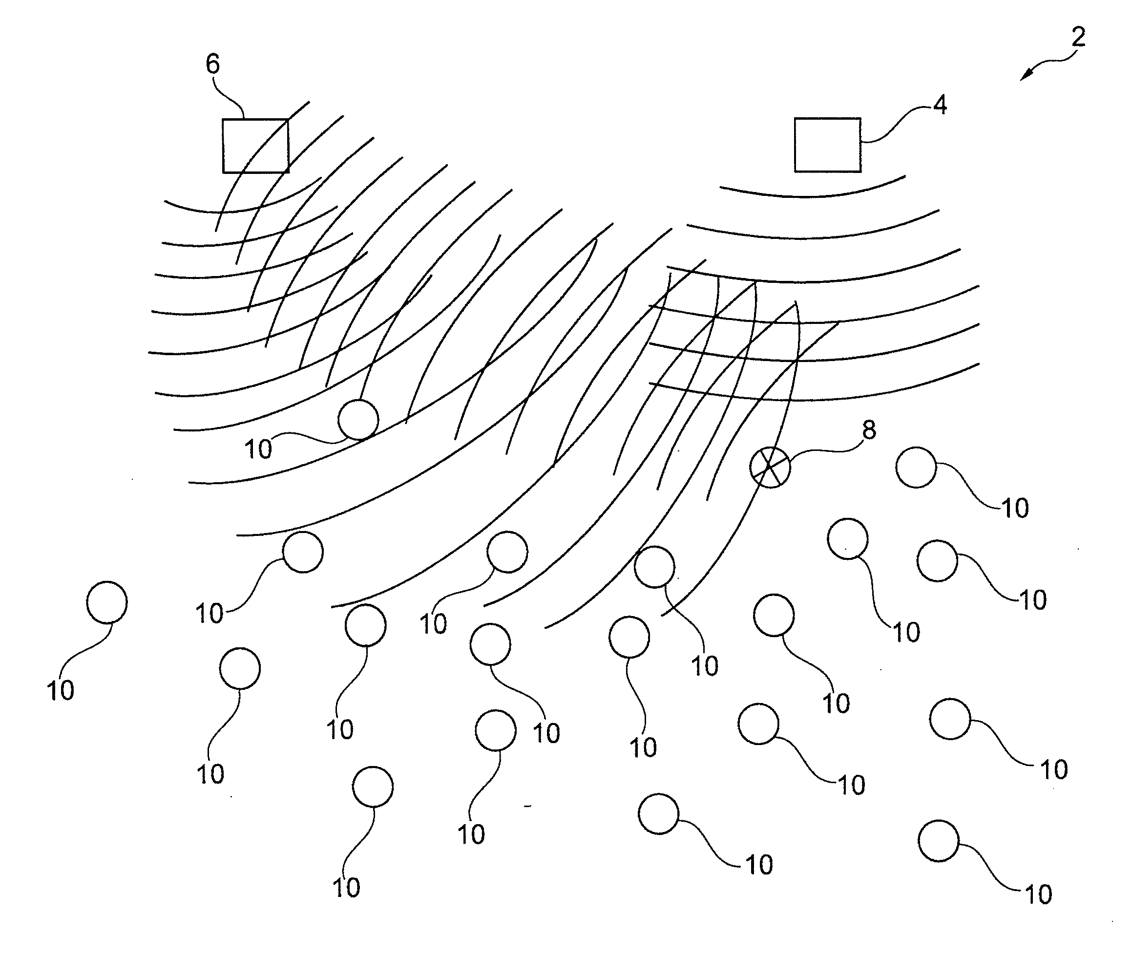
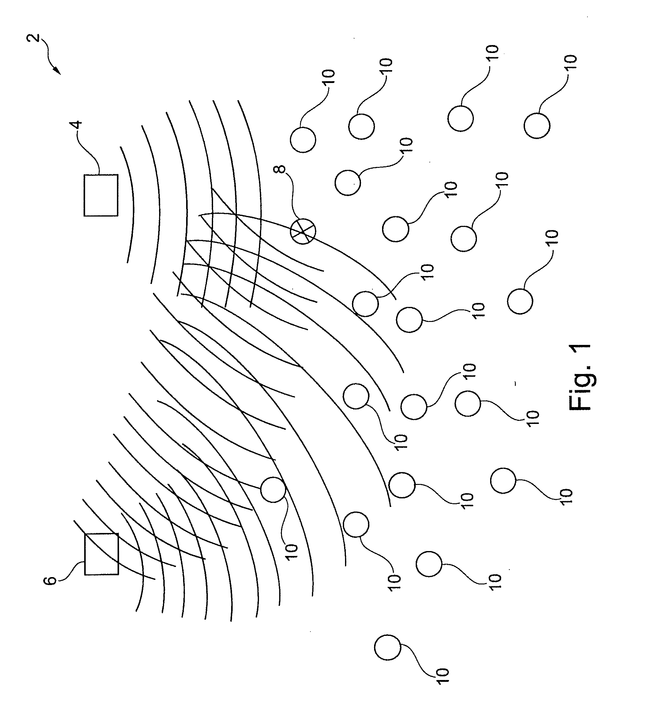
[0019]This may be achieved by a system as specified in the preamble of claim 1 if communication between the fixed transceiver facilities and the electronic transceiver units occurs in an ultra wideband frequency spectrum in a frequency range from 3.10 GHz to 10.6 GHz, wherein communication occurs in the form of transient pulses emitted from the electronic transceiver units, and where position determination is performed by calculating time or phase difference between receptions of a signal at least two transceiver facilities, respectively.

[0020]By using high frequency wideband communication, it becomes possible to determine the position of the movable objects with very high accuracy. In principle, positioning may be performed down to fractions of a wavelength for the given frequency by an efficient phase differential measurement, but in practice, where reflection of signal may occur, there may be expected an accuracy possibly corresponding to one or more wavelengths. By this inventio...


PUM


Abstract

The present invention concerns a system for detecting and determining the position of moving objects, where electronic transceiver units communicate with at least two fixed transceiver stations. It is the object of the invention to perform a constant position determination of movable objects within a delimited area. This may be achieved if communication between the fixed transceiver facilities and the electronic transceiver units occurs in an ultra wideband frequency spectrum in a frequency range from 3.10 GHz to 10.6 GHz, wherein communication occurs in the form of transient pulses emitted from the electronic transceiver units, and where position determination is performed by calculating time or phase difference between receptions of a signal at least two transceiver facilities, respectively. By using high frequency wideband communication, it becomes possible to determine the position of the movable objects with very high accuracy.

Description

BACKGROUND OF THE INVENTION[0001]1. Field of the Invention[0002]The present invention concerns a system for detection and position determination of movable objects, the objects being provided with an electronic transceiver unit which by reception of a first signal emits a second signal, the second signal containing a unique information code related to a movable object, where the electronic transceiver units communicate with at least two fixed transceiver facilities connected with at least one computer.[0003]2. Description of Related Art[0004]The present invention is further related to a method for indicating normal or abnormal behaviour of animals, such as cattle, where the animals carries detector means, which detector means communicate with processor means carried by the animal, and the processor carried by the animal further communicates with a central processor.[0005]US 2007 / 0008150 disclose a cattle identification system operating across long distances. This publication concern...

Claims


Application Information

Patent Timeline
Patent Type & Authority Applications(United States)
IPC IPC(8): H04Q5/22
CPCA01K29/005G01S5/06G01S13/0209G01S13/867G01S13/878G01S13/88G01S13/76A01K11/006
Inventor HINDHEDE, AAGE
Owner SMARTER FARMING
Why Eureka
Try Eureka