Capacitive touch panel

a capacitive touch and touch technology, applied in the field of capacitive touch panels, can solve the problem that the capacitive touch panel b>100/b> has partial hue error when displaying images, and achieve the effect of improving the display quality, reducing the gap between the sensing units, and increasing the color uniformity

Inactive Publication Date: 2011-05-05
TRANSTOUCH TECH
View PDF3 Cites 15 Cited by
  • Summary
  • Abstract
  • Description
  • Claims
  • Application Information

AI Technical Summary

Benefits of technology

[0008]The invention is directed to a capacitive touch panel. The sensing units disposed on the same plane are adjacent to one another, so that the gap between the sensing units is reduced, not only increasing the color uniformity on the surface of the capacitive touch panel but also improving the display quality of the capacitive touch panel.

Problems solved by technology

Thus, the capacitive touch panel 100 has partial hue error when displaying an image.

Method used


Image

  • Capacitive touch panel
  • Capacitive touch panel
  • Capacitive touch panel

Examples


Embodiment Construction

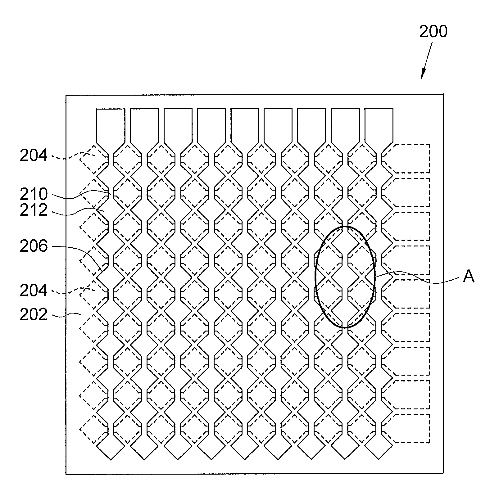
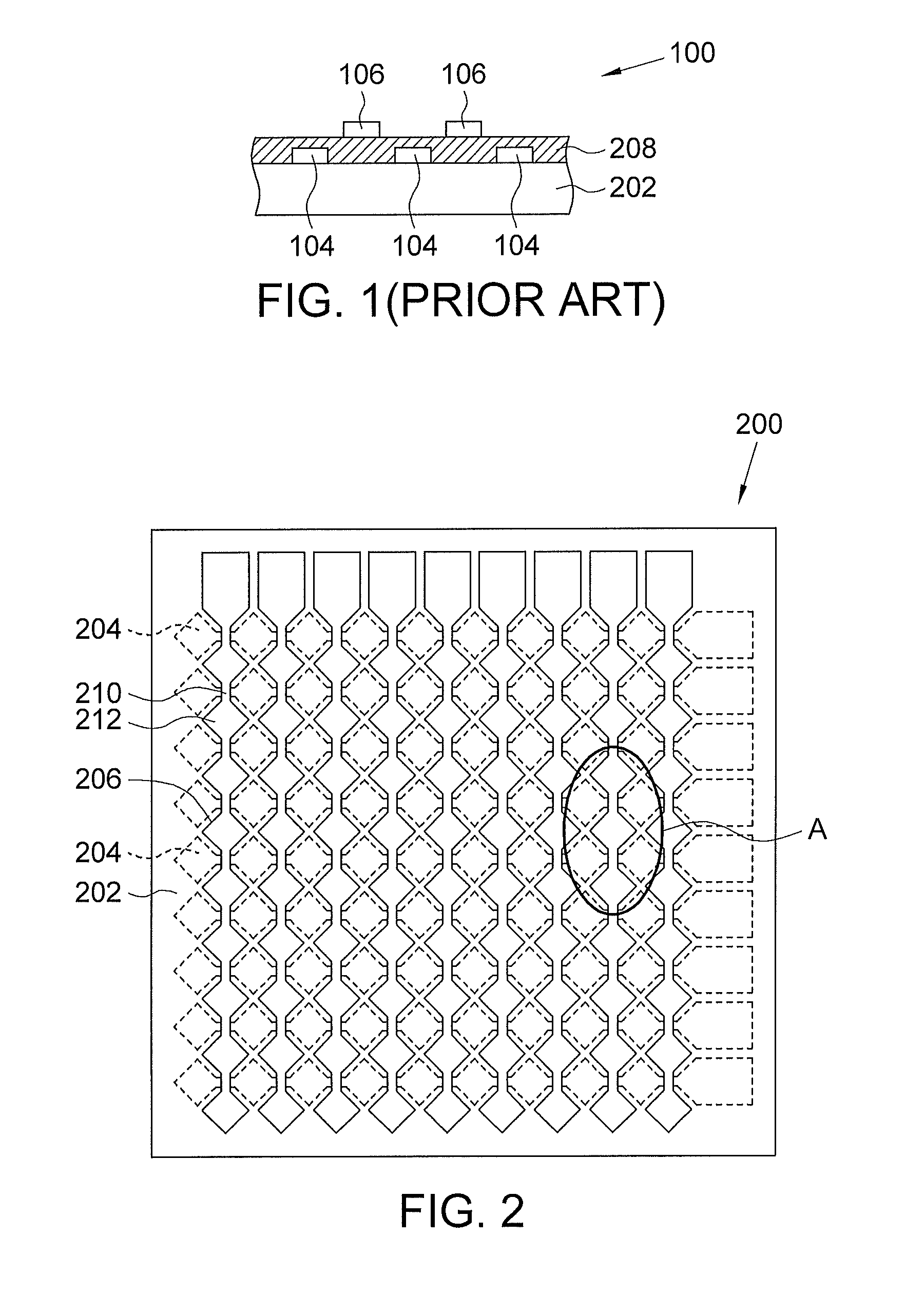
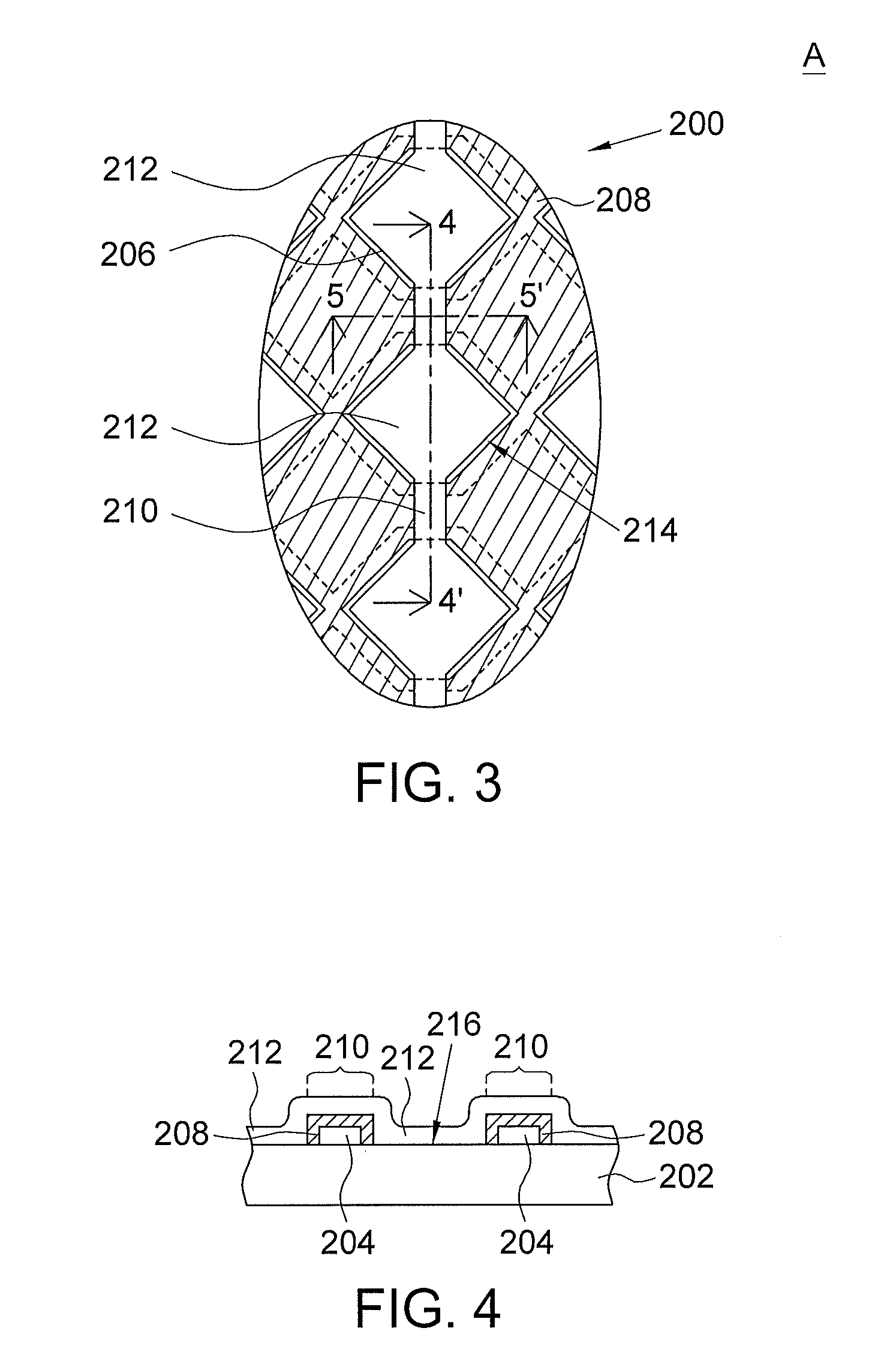
[0017]Referring to FIG. 2 and FIG. 3. FIG. 2 shows a capacitive touch panel according to a preferred embodiment of the invention. FIG. 3 shows a partial enlargement A of FIG. 2.

[0018]As indicated in FIG. 2, the capacitive touch panel 200 includes a transparent substrate 202, a plurality of first sensing wires 204, a plurality of second sensing wires 206 and an insulation layer 208 (illustrated in FIG. 3). To simplify the illustration, the insulation layer 208 is not illustrated in FIG. 2.

[0019]The transparent substrate 202 can be made from an insulating material with high transmittance such as polycarbonate (PC), polythylene terephthalate (PET), polymethylmethacrylate (PMMA) or cyclic olefin copolymer.

[0020]The second sensing wires 206 and the first sensing wires 204 can be made from indium tin oxide (ITO) or a transparent organic conductive material such as 3,4-ethylenedioxythiophene (PEDOT).

[0021]The first sensing wires 204 can be arranged along a first axis direction, and the sec...


PUM


Abstract

A capacitive touch panel including a transparent substrate, a plurality of first sensing wires, a plurality of second sensing wires and an insulation layer is provided. The transparent substrate has a substrate surface. The first sensing wires are disposed on the substrate surface along a first axis direction. The second sensing wires include a plurality of bridge wires and a plurality of sensing units. The sensing units are disposed on the substrate surface along the second axis direction. The insulation layer is disposed on the substrate surface, covers the first sensing wires, and has a plurality of through holes. The through holes correspondingly expose the sensing units. Each bridge wire strides the insulation layer to electrically connect two of the sensing units.

Description

[0001]This application claims the benefit of Taiwan application Serial No. 98220396, filed Nov. 4, 2009, the subject matter of which is incorporated herein by reference.BACKGROUND OF THE INVENTION[0002]1. Field of the Invention[0003]The invention relates in general to a capacitive touch panel, and more particularly to a capacitive touch panel whose insulation layer has through holes.[0004]2. Description of the Related Art[0005]Referring to FIG. 1 (prior art), a capacitive touch panel is shown. The capacitive touch panel 100 includes a substrate 102, a plurality of X-axis sensing wires 104, a plurality of Y-axis sensing wires 106 and an insulation layer 108.[0006]The X-axis sensing wires 104 are disposed on the substrate 102. The insulation layer 108 covers the X-axis sensing wires 104 and separates the X-axis sensing wires 104 from the Y-axis sensing wires 106.[0007]Conventionally, the X-axis sensing wires 104 and the Y-axis sensing wires 106 are disposed on the different planes, an...

Claims


Application Information

Patent Timeline
Patent Type & Authority Applications(United States)
IPC IPC(8): G06F3/045
CPCG06F2203/04111G06F3/044G06F3/0446
Inventor WANG, WEI-WENCHEN, TING-CHIEHTEO, BOON-HOCKLIN, SHENG-HSIENKUO, YUH-RURMA, SHIH-HSIEN
Owner TRANSTOUCH TECH
Why Eureka
Try Eureka