Planetary gear reduction system

a gear reduction and gear technology, applied in the direction of gears, efficient propulsion technologies, machines/engines, etc., can solve the problems of uneven bearing support of ring gears and gears making improper engagements, and deflection of circumferential journals of planet gears, so as to reduce the rigidity of the first plate, minimize circumferential deflection, and increase the life span of the system

Active Publication Date: 2011-05-05
KAWASAKI HEAVY IND LTD
View PDF6 Cites 36 Cited by
  • Summary
  • Abstract
  • Description
  • Claims
  • Application Information

AI Technical Summary

Benefits of technology

[0015]According to the invention, the rigidity of the first plate is reduced relative to the second plate by means of the first and second cutouts provided around the first portions, which effectively minimizes circumferential deflections of the planet shafts and the non-parallelisms of the planet shafts relative to the central axis of the system to retain suitable engagements between the planet and the sun gears and also the planet and the ring gears. Also, the life spa of the system is increased. Further, the cutouts reduces the total weight of the system.
[0016]In another aspect of the invention, the each of the second cutouts has a first cutout portion extending radially inwardly from the first region and a pair of second cutout portions extending radially inwardly from a radially inward end of the first cutout portion and diverging in opposite circumferential directions toward neighboring first portions, respectively. This arrangement effectively reduces the rigidity of the portions around the support portion while keeping a structural strength needed for the first plate.
[0017]In another aspect of the invention, the each of the second cutouts extends 50 percent or more of an annular region in a radial direction. The annular region is a ring-like zone which crosses through internal cylindrical cavities of the planet shafts and is defined between a circumscribed circle which circumscribes the cylindrical cavities of the planet shafts and an inscribed circle which inscribes the cylindrical cavities. This arrangement effectively reduces the rigidity of the first plate.
[0018]In another aspect of the invention, the second portion is deviated relative to the first portion in a direction parallel to a central axis of the sun gear. This arrangement increases a distance between the first and second portions, which effectively reduces the rigidity of the first plate.
[0019]In another aspect of the invention, the first plate is made as a separate part of the planet carrier and is connected to the drum through the second portions thereof. This arrangement allows the planet carrier to reduce the rigidity of its first plate easily.

Problems solved by technology

In operation of the aircraft equipped with the planetary gear reduction system, the journal shafts of the planet gears tend to deflect or skew circumferentially due to torque forces applied to the planet carrier.
This may cause the journal shafts of the planet gears out of parallel to the axis of the sun gear, which in turn results in that the planet gears make improper engagements with the sun gear and the ring gear and the journals of the planet gears become unevenly supported by their bearings.

Method used


Image

  • Planetary gear reduction system
  • Planetary gear reduction system
  • Planetary gear reduction system

Examples


Embodiment Construction

[0026]The following descriptions of the preferred embodiments are merely exemplary in nature and are in no way intended to limit the invention, its application, or uses.

[0027]Hereinafter, preferred embodiments of the present invention will be described with reference to the accompanying drawings. Although not limited thereto, the planetary gear reduction system according to the present invention is preferably used with, for example, gas turbine engines.

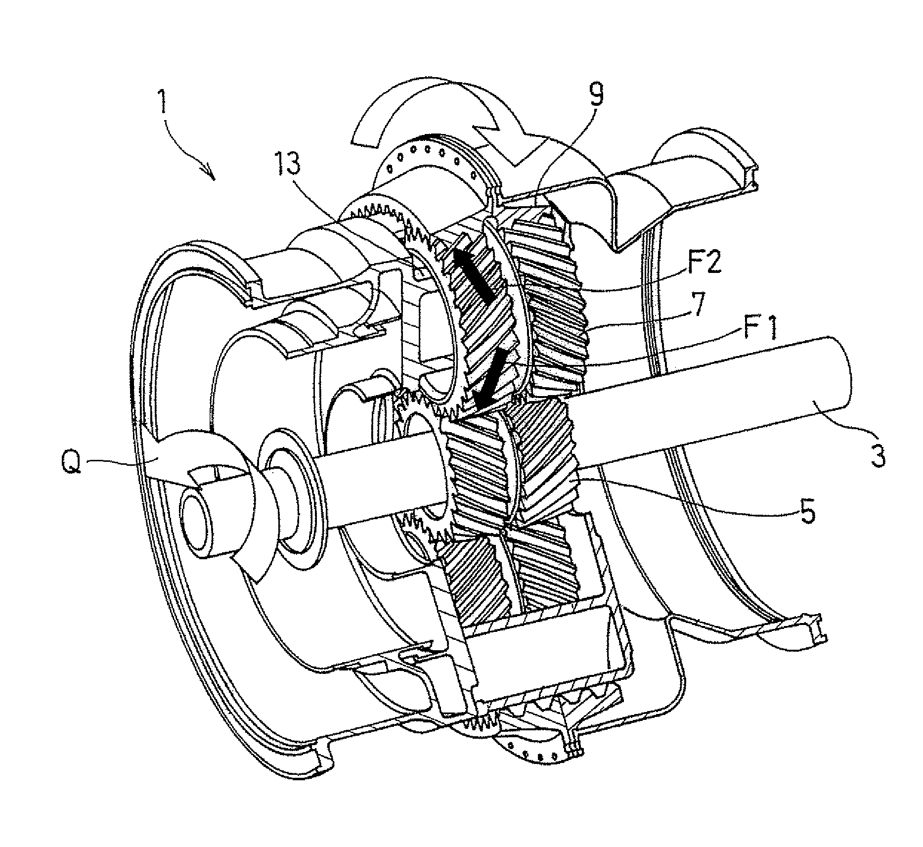
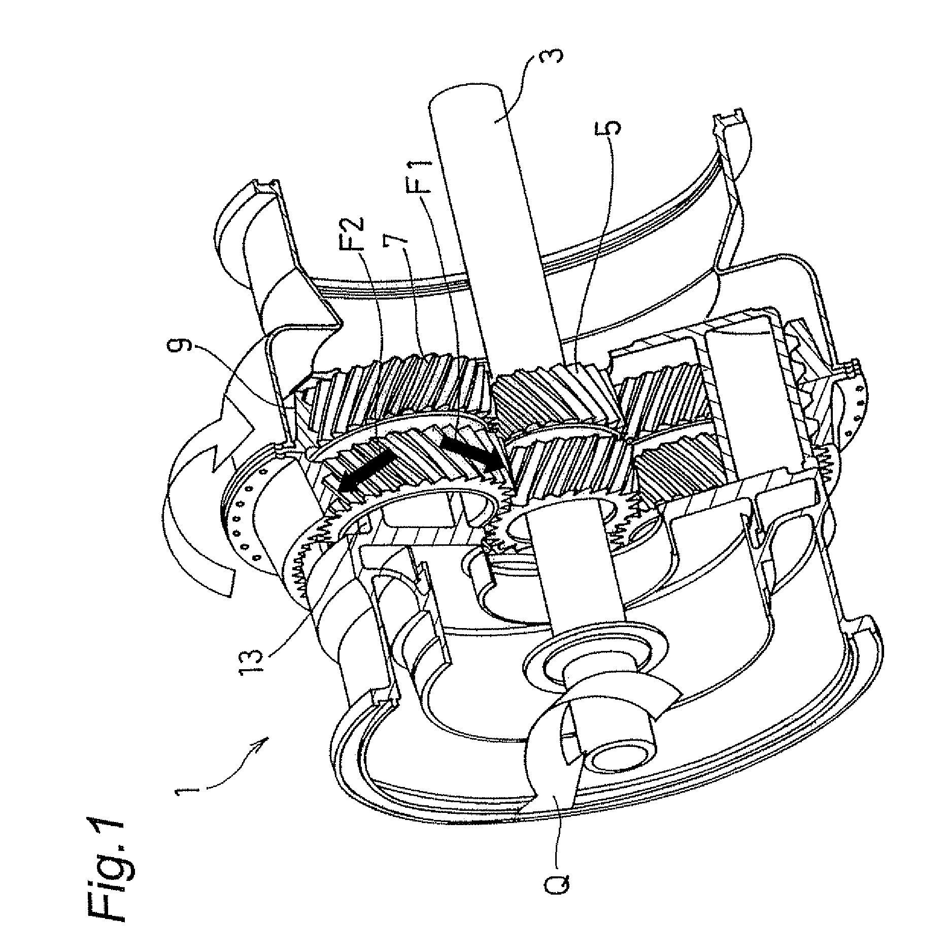
[0028]With reference to the accompanying drawings, preferred embodiments according to the present invention will be described below. FIG. 1 is a perspective view of a planetary gear reduction system, generally indicated by reference numeral 1, according to the present invention. The planetary gear reduction system 1 may be used with an engine of the aircraft and helicopter. In this instance, the system 1 is drivingly connected to the gas turbine engine through an input shaft 3 so that the driving force from the engine is transmitted t...


PUM


Abstract

A planetary gear reduction system has a sun gear, a plurality of planet gears, a ring gear, and a planet carrier. The planet carrier has a first plate supporting one ends of planet shafts supporting the planet gears, a second plate supporting the other ends of the planet shafts, and a cylindrical drum connecting the first and second plates. The first plate has first portions supporting the one ends of the planet shafts; second portions connecting the first plate to the drum, the first and second portions being provided alternately in a circumferential direction; first cutouts each defined between the neighboring first and second portions, the first cutouts each extending radially inwardly from a circumferential edge thereof to a position adjacent a circle passing centers of the planet shafts; and second cutouts each defined radially inward of the second portion and between the neighboring two first portions, the second cutouts each extending radially inwardly from a first region outside the circle and a second region inside the circle.

Description

FIELD OF THE INVENTION[0001]The present invention relates to a planetary gear reduction system for use in particular in a drive force transmission mechanism of an aircraft.BACKGROUND OF THE INVENTION[0002]A conventional planetary gear reduction system has a sun gear having external tooth, a plurality of planet gears each having external tooth in meshing engagement with the external tooth of the sun gear, a common planet carrier supporting journal shafts of the planet gears for establishing relative positions of the planet gears, and a ring gear having internal tooth in meshing engagement with external tooth of the planet gears. With the arrangement, the drive force generated at the drive source such as a gas turbine engine is transmitted to the sun gear and then to the planet gears. The drive force transmitted to the planet gears are outputted in two different ways, for example, in the form of rotational force of the ring gear which is caused by the rotational motions of the planet ...

Claims


Application Information

Patent Timeline
Patent Type & Authority Applications(United States)
IPC IPC(8): F16H1/28
CPCF02C7/36F16H1/2836F16H57/082F05D2260/40311Y02T50/671Y02T50/60
Inventor MATSUOKA, TETSUYANISHIKAWA, HIROYASUNISHIDA, TOORUAKAHORI, HIROFUMIIMAI, HIDEYUKIGOI, TATSUHIKO
Owner KAWASAKI HEAVY IND LTD
Why Eureka
Try Eureka