
System and method for hernia mesh fixation

a system and mesh technology, applied in the field of systems and methods, can solve the problems of repairing hernias, restricting blood flow to the tissue, pain or strangulation of the bowel, etc., and achieve the effect of preventing tissue damage and allowing transfacial fixation

Inactive Publication Date: 2011-05-05
MASSACHUSETTS INST OF TECH +1
View PDF79 Cites 27 Cited by
  • Summary
  • Abstract
  • Description
  • Claims
  • Application Information

AI Technical Summary

Benefits of technology

[0015]In accordance with a further aspect, the fastener may be disposed in an undeployed state within an introducer portion of the delivery system. In accordance with one embodiment, the introducer portion may be movably disposed within a main body portion of the delivery system. The distal end of the main body portion of the delivery system may be blunt to prevent damage to tissue, and the introducer portion may have a sharpened distal tip that may be advanced out of the distal end of the main body portion of the delivery system and advanced through fascia to permit transfascial fixation.

Problems solved by technology

A weakness in the abdominal wall, for example caused by a former surgical incision, may allow the internal organs to pass through, causing a hernia.
Hernias are relatively common and may cause pain or strangulation of the bowel, in which blood flow to the tissue is restricted.
The laparoscopic method for repairing hernias may cause several problems.
For example, transfascial sutures can often cause excessive post-operative pain.
The sutures, in turn, concentrate these forces causing pain.
Moreover, sutures have relatively low compliance compared to abdominal tissues, and therefore sutures may “pinch” when the muscle tissue contracts, similarly causing irritation to surrounding tissue.
Furthermore, metal tacks (as described above) may occasionally dislodge from the abdominal wall, permitting them to irritate other tissue as they move within the body.
Without the fasteners to hold the mesh in place, the mesh may come loose.
These events may lead to additional complications, and possibly additional surgery.

Method used


Image

  • System and method for hernia mesh fixation
  • System and method for hernia mesh fixation
  • System and method for hernia mesh fixation

Examples


Embodiment Construction

[0041]Reference will now be made in detail to the present preferred embodiments of the invention, examples of which are illustrated in the accompanying drawings. The method and corresponding steps of the invention will be described in conjunction with the detailed description of the system.

[0042]Devices and methods provided in accordance with the invention may be used generally in surgical procedures. Such devices and methods are particularly advantageous in affixing mesh to tissue in the course of surgery to repair a hernia defect.

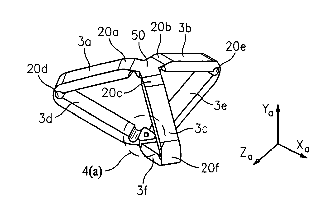
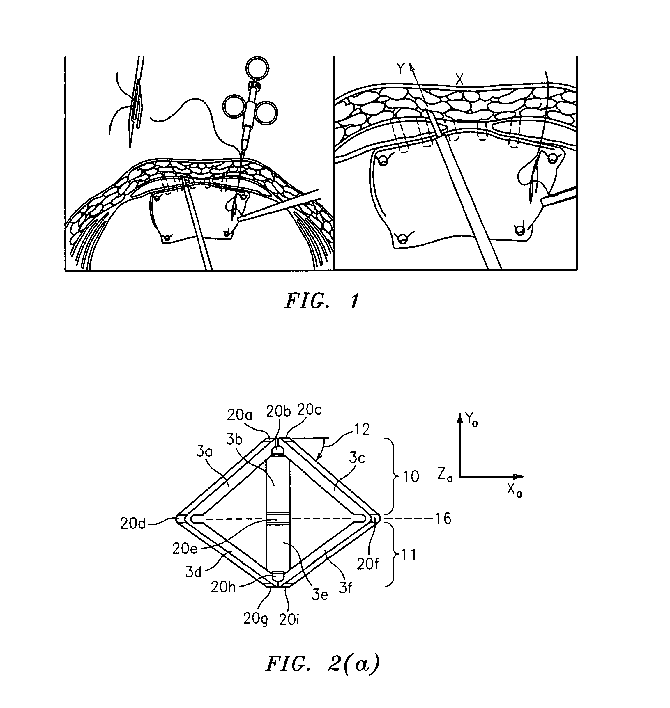
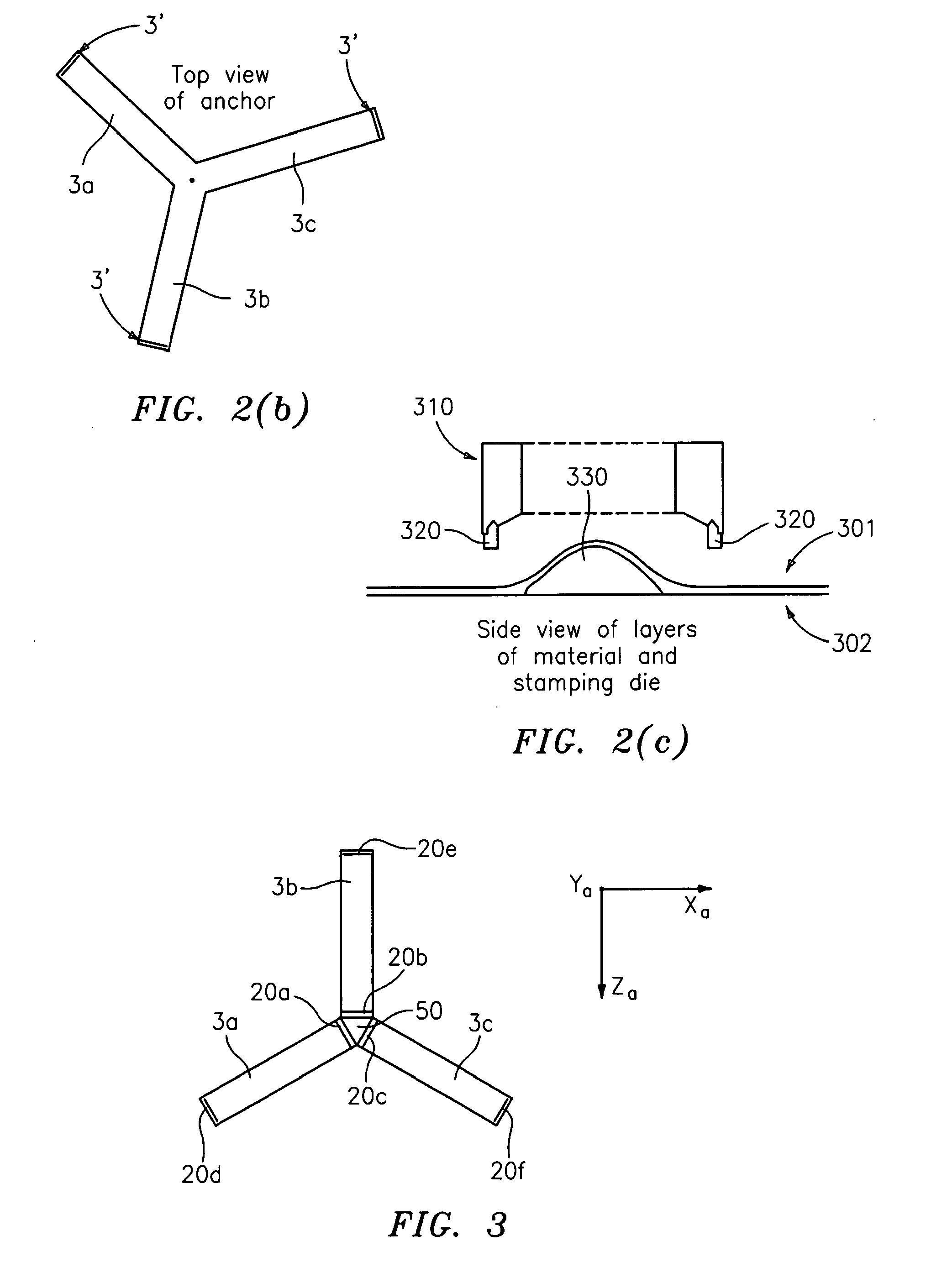
[0043]For purposes of illustration, and not limitation, exemplary embodiments of devices and methods provided by the invention are illustrated in FIGS. 2-21 herein. In accordance with a first embodiment, an improved fastener is provided that may be delivered using a delivery system.

[0044]As embodied herein and as depicted in FIG. 2(a), the fastener includes an anchor head portion 29. Various views of the fastener of FIG. 2(a) are provided in FIGS. 3-12 an...


PUM


Abstract

The invention includes a surgical fastener and associated deployment system and method that overcomes the drawbacks of prior art surgical mesh fixation devices. The surgical fastener and deployment system may be used to fixate a surgical mesh material to the abdominal wall for the purpose of hernia repair. In accordance with one embodiment, the fastener may include an anchor head comprising a bi-pyramid framework. The anchor head is preferably made from a highly deformable and biocompatible material that withstands high flexural strain within an oscillatory environment. The anchor head may be provided in an elongate, undeployed configuration, and then expanded during deployment into a second, generally planar configuration. The anchor head may be biased to expand into the generally planar configuration from the undeployed configuration in a variety of manners.

Description

CROSS-REFERENCE TO RELATED APPLICATION[0001]This application claims priority to U.S. Provisional Patent Application Ser. No. 60 / 959,343, Filed Jul. 13, 2007. This patent application is incorporated by reference herein in its entirety.BACKGROUND OF THE INVENTION[0002]1. Field of the Invention[0003]The present invention relates to systems and methods for attaching a prosthetic device to the surface of tissue, and more particularly, to the application of mesh to cover a hernia defect as well as devices for applying such a mesh and holding such mesh in a desired position.[0004]2. Description of Related Art[0005]The anterior abdominal wall is comprised of a muscle layer, surrounded by strong connective tissue known as fascia. Adipose tissue (fat) and dermal layers (skin) are located on the outside of the muscle layer. A weakness in the abdominal wall, for example caused by a former surgical incision, may allow the internal organs to pass through, causing a hernia. Hernias are relatively ...

Claims


Application Information

Patent Timeline
Patent Type & Authority Applications(United States)
IPC IPC(8): A61B17/00
CPCA61B17/064A61B2017/0641A61B17/10A61B17/0684
Inventor TAVAKKOLIZADEH, ALIEILENBERG, MICHAELGALIE, JESSICAROBERTS, MEGANCULPEPPER, MARTIN
Owner MASSACHUSETTS INST OF TECH
Learn More