Apparatus for implementing a spinal fixation system with supplemental fixation

a spinal fixation system and apparatus technology, applied in the field of spinal fixation systems, can solve the problems of not being strong enough to hold the intended correction, not being able to meet the typical situation of surgeons, and not being able to meet the needs of lateral aspect, etc., to achieve the effect of enhancing the spinal fixation system, and enhancing the fixation strength of the spinal fixation rod assembly

Active Publication Date: 2011-05-05
WARSAW ORTHOPEDIC INC
View PDF19 Cites 38 Cited by
  • Summary
  • Abstract
  • Description
  • Claims
  • Application Information

AI Technical Summary

Benefits of technology

[0007]The present invention meets this need by providing an innovation that works around the weakened vertebral component, such as a pedicle, and enhances the spinal fixation system by employing supplemental fixation from an adjacent vertebral component, such as a lamina, on the same vertebrae as the pedicle. The innovation relates to a supplemental fixation device employed in the spine fixation system to augment the fixation strength of a spinal fixation rod assembly by providing additional or supplemental fixation at a secondary fixation point located in the adjacent lamina offset from the alignment of the primary fixation points of the spinal fixation rod assembly in the remaining pedicles on either side of the weakened pedicle. This innovation will allow additional construct strength especially for those patients that have osteoporotic bone. Use of the supplemental device further allows the spinal fixation rod to maintain the traditional trajectory of the top-loading, top-tightening spinal fixation system.

Problems solved by technology

However, this is not the typical situation surgeons face in the case of patients with osteoporotic bone conditions.
Uncertainty regarding the strength of vertebrae is always present in patients with osteoporotic bone.
Oftentimes one vertebral component, such as one pedicle of a plurality thereof where a particular level of fixation is planned, may have a lateral aspect that is not strong enough to hold the intended correction.

Method used


Image

  • Apparatus for implementing a spinal fixation system with supplemental fixation
  • Apparatus for implementing a spinal fixation system with supplemental fixation
  • Apparatus for implementing a spinal fixation system with supplemental fixation

Examples


Embodiment Construction

[0017]The present invention now will be described more fully hereinafter with reference to the accompanying drawings, in which some, but not all embodiments of the invention are shown. Indeed, the invention may be embodied in many different forms and should not be construed as limited to the embodiments set forth herein; rather, these embodiments are provided so that this disclosure will satisfy applicable legal requirements. Like numerals refer to like elements throughout the views.

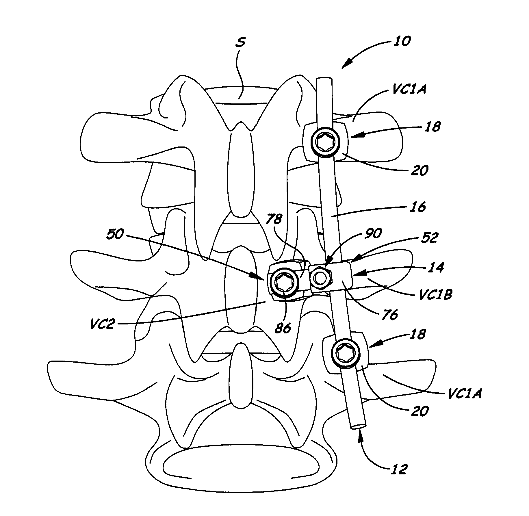
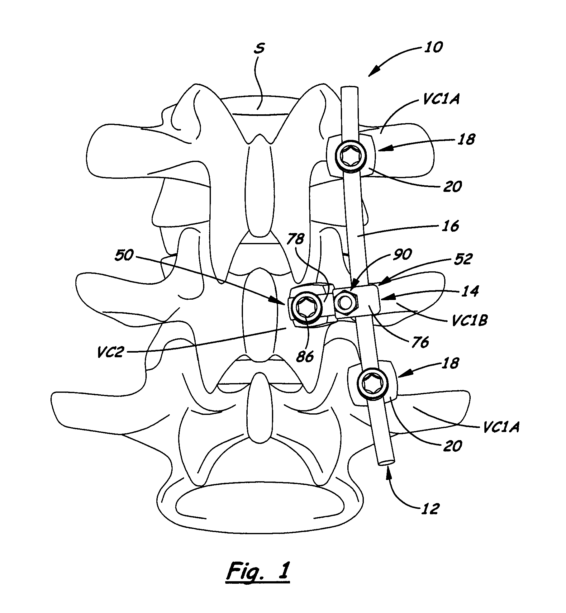
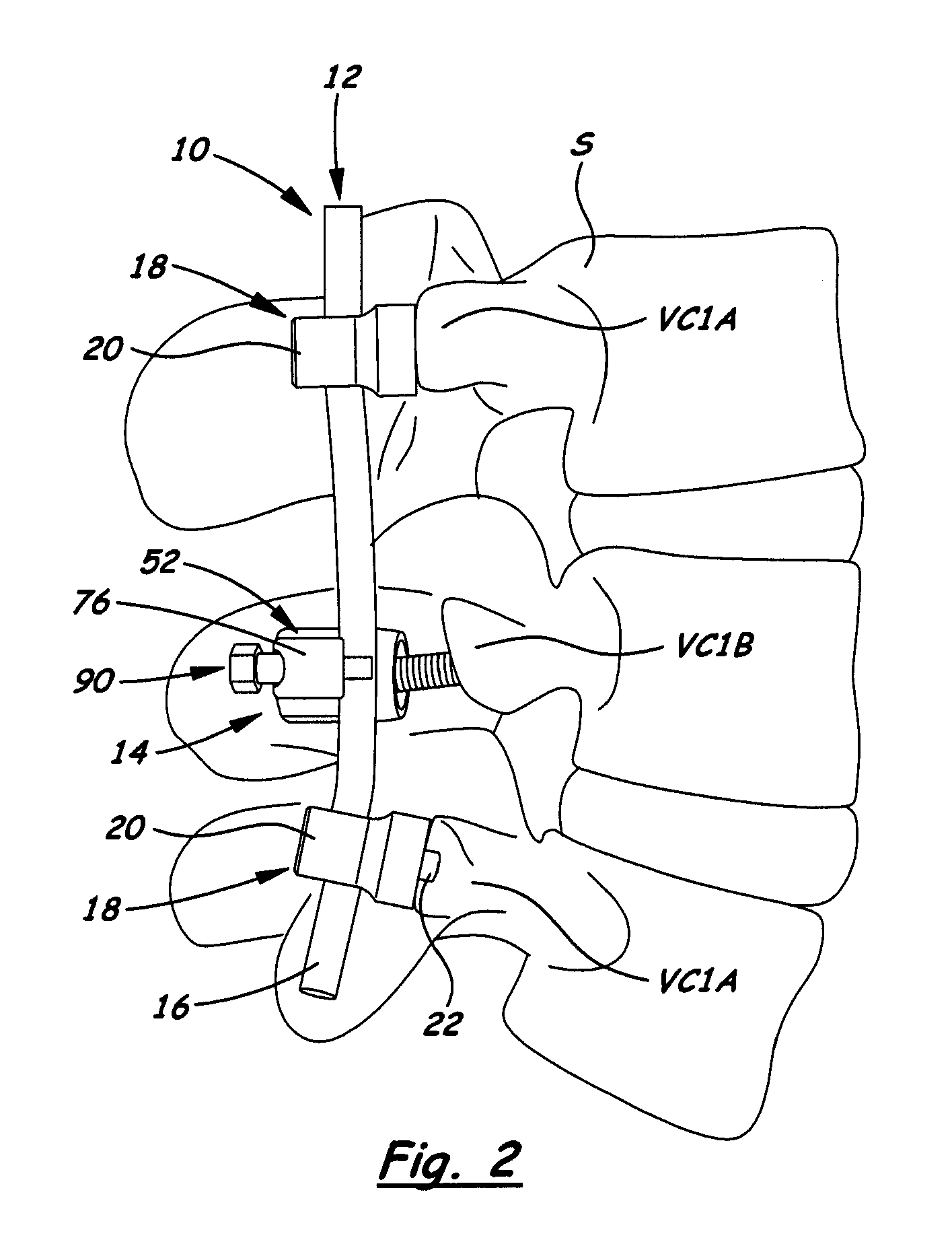
[0018]Referring now to FIGS. 1 and 2, there is illustrated a spinal fixation system in accordance with the present invention showing an exemplary embodiment of an apparatus, generally designated 10, for implementing the system with supplemental fixation. The implementing apparatus 10 basically includes a spinal fixation rod assembly 12 and at least one supplemental fixation device 14. The spinal fixation rod assembly 12 is adapted to provide primary fixation at a plurality of first fixation loci or point...


PUM


Abstract

An apparatus for implementing a spinal fixation system with supplemental fixation includes a spinal fixation rod assembly and at least one supplemental fixation device. The spinal fixation rod assembly is adapted to provide primary fixation at a plurality of first fixation points by being secured to a plurality of first vertebral components except not into one of the first vertebral components of the plurality that is in a weakened structural condition and located between other of the first vertebral components of the plurality. The supplemental fixation device is adapted to provide supplemental fixation for the assembly at a second fixation point by being secured to a second vertebral component located adjacent to and offset from the one first vertebral component in the weakened structural condition and also to interconnect with the assembly to provide anchorage and thus additional fixation supplemental to the primary fixation.

Description

BACKGROUND[0001]1. Field of the Invention[0002]The present invention relates generally to spinal fixation systems and, more particularly, to an apparatus for implementing a spinal fixation system with supplemental fixation.[0003]2. Description of the Related Art[0004]Spinal fixation systems typically employ a spinal rod for supporting the spine and properly positioning vertebrae of the spine for various treatment purposes. Devices such as bolts, screws, clamps and hooks are typically secured to the vertebrae for connection to the supporting spinal rod. Examples of some known spinal fixation systems are disclosed in U.S. Pat. Nos. 5,209,752 and 5,562,662.[0005]With most spinal conditions to be corrected, surgeons can typically anticipate that the vertebral components where these devices are to be implanted or attached will normally have sufficient strength and integrity to accommodate the devices. However, this is not the typical situation surgeons face in the case of patients with o...

Claims


Application Information

Patent Timeline
Patent Type & Authority Applications(United States)
IPC IPC(8): A61B17/70A61B17/86
CPCA61B17/7041A61B17/7037
Inventor WILCOX, BRYAN S.COWAN, BENJAMIN D.BALLARD, RODNEY R.LINDENMAN, HEATHER
Owner WARSAW ORTHOPEDIC INC
Why Eureka
Try Eureka