Reaction assembly and flow splitter

Inactive Publication Date: 2011-05-12
AVANTIUM HLDG BV
View PDF16 Cites 4 Cited by
  • Summary
  • Abstract
  • Description
  • Claims
  • Application Information

AI Technical Summary

Benefits of technology

[0010]The object of the invention is to provide an im

Problems solved by technology

In practice, it has turned out that the system known from WO99/64160 is not suitable for experiments in which the flow rate of the secondary fluid flows and/or the ratio between the flow rates of the secondary fluid flows has to be controlled accurately, especially when small scale experiments are performed, for example experiments with flow rates below 2 ml/min.
Obtaining substantially equal flow rates for all secondary fluid flows is a cumbersome process, as it requires individual calibration and adaptation of all capillaries in order to obtain the desired flow resistance for each capillary.
This is a painstaking process as it is hard to make the cuts accurately enough and often too much is cut off, which means you have to start all over again.
To do this

Method used


Image

  • Reaction assembly and flow splitter
  • Reaction assembly and flow splitter
  • Reaction assembly and flow splitter

Examples


first embodiment

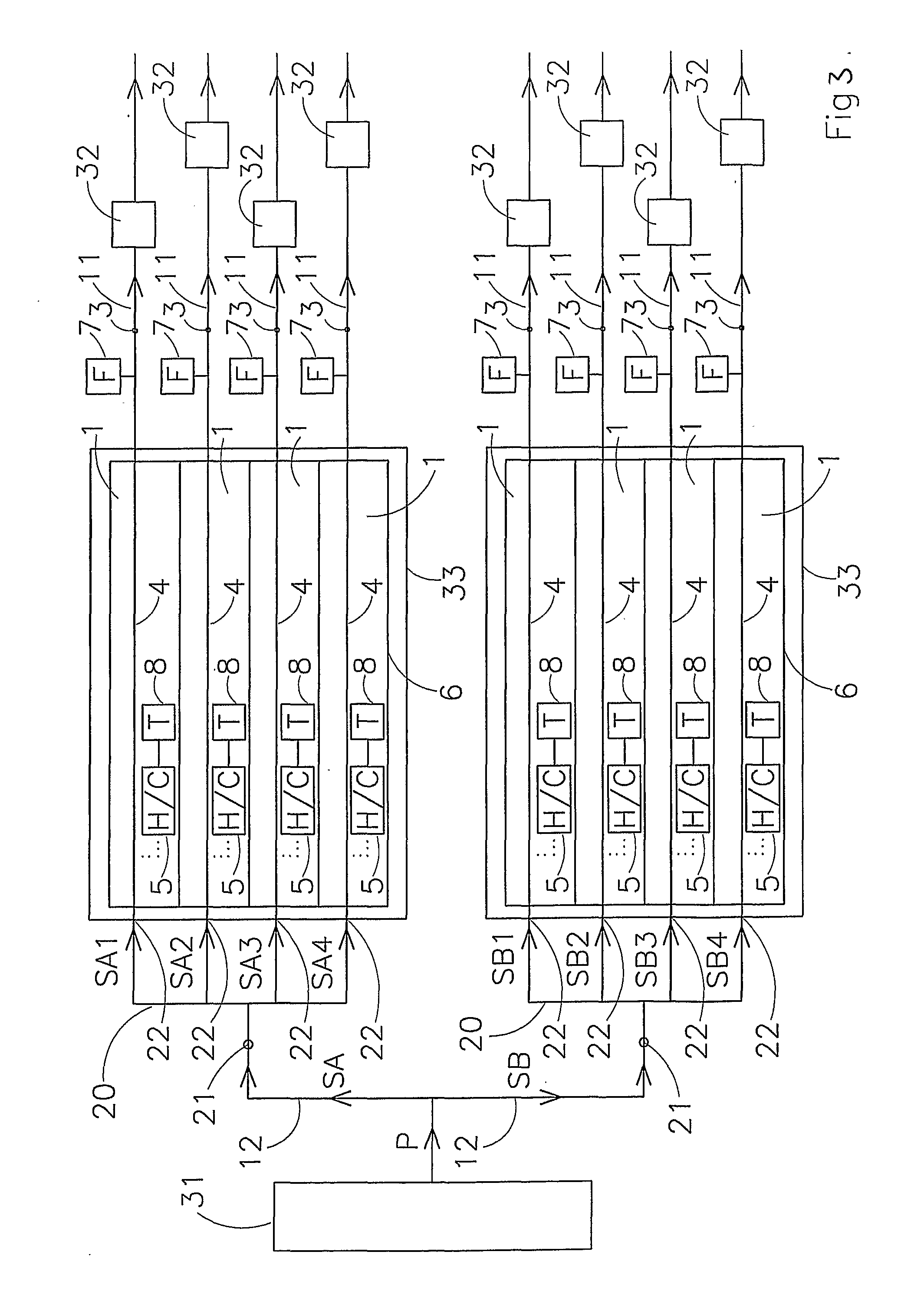
[0080]FIG. 3 shows a reaction system according to the invention. This reaction system comprises a fluid supply unit 31 for supplying a primary fluid flow P. The reaction system further comprises in this example two manifolds 20, that each have four capillary units 1 connected to them. The skilled person will understand that any other number of manifolds and / or capillary units is also possible. Connection lines 12 connect the fluid supply unit 31 to the manifolds 20. The primary fluid flow P is first divided into flows SA and SB. The first flow splitter divides flow SA into secondary fluid flows SA1, SA2, SA3 and SA4. The second flow splitter divides flow SB into secondary fluid flows SB1, SB2, SB3 and SB4.

[0081]In the embodiment of FIG. 3, the housings 6 of the capillary units 1 connected to the same manifold 20 are arranged together in a cassette 33. This allows easy mounting into a reaction system setup, for example in a rack. It also allows a fast exchange of sets of capillary un...

second embodiment

[0091]FIG. 4 shows a reaction system according to the invention. In this embodiment, the reaction system comprises a first fluid supply unit 41 and a second fluid supply unit 42. The first fluid supply unit 41 delivers a first primary fluid flow F1 at a first pressure p1. The second fluid supply unit 42 delivers a second primary fluid flow F2 at a second pressure p2. It is possible that p1 is equal to p2, but the system is in particular suitable for situations in which p1 and p2 are different. It is also suitable for a system in which parallel reactions are carried out using different fluids.

[0092]Downstream of first fluid supply unit 41, first capillary unit 40* is arranged. First capillary unit 40* is a capillary unit according to the invention, for example a first capillary unit according to FIG. 1. The first fluid supply unit 41 is connected to first capillary unit 40* by supply line 10*. Downstream of the first capillary unit 40*, discharge line 11* is arranged for supplying fi...

third embodiment

[0097]FIG. 5 shows a reaction system according to the invention. In this embodiment, capillary units according to the invention are used as part of a back pressure control system.

[0098]In the reaction system according to FIG. 5, a plurality of reaction vessels 32 is provided. Each reaction vessel 32 is provided with at least one reaction vessel inlet 34 and at least one reaction vessel outlet 35. A primary fluid flow P is supplied to the system, which is then in this example split up into secondary fluid flows S1, S2 and S3. For this flow splitting, a flow splitter according to the invention, for example a flow splitter according to FIG. 7, can be used, but this is not necessary. In the reaction system of FIG. 5, each of the reaction vessels 32 is provided with a reaction vessel effluent line 50 for discharging the reaction effluent from that particular reaction vessel 32. The reaction vessel effluent line 50 is connected to the reaction vessel outlet 35 of the associated reaction v...


PUM


Abstract

The invention pertains to reaction systems in which at least one capillary unit is applied. The capillary unit comprises: —a unit inlet for receiving a fluid flow, —a unit outlet for releasing said fluid flow, —a capillary, which capillary is arranged between the unit inlet and the unit outlet such that said fluid flow passes through the capillary, —a heater and/or a cooler for adjusting the temperature of the capillary and therewith influencing the flow rate of the fluid flow passing through said capillary, —a housing for accommodating at least the capillary and heater and/or cooler of said capillary unit, which housing provides thermal insulation of the capillary, —a flow sensor for measuring the flow rate of the fluid flow through the capillary unit, which flow sensor can be arranged either inside or outside the housing, A capillary unit is combined with or further has a flow adjustment unit for adjusting the flow rates of the secondary fluid flows, which flow adjustment unit comprises a temperature control device for individually controlling the heater and/or cooler of each capillary unit in response to the flow rate that is measured by the flow sensor of that capillary unit.

Description

CROSS-REFERENCE TO RELATED APPLICATIONS[0001]This application is the National Stage of International Application No. PCT / NL2009 / 000122, filed May 26, 2009, which claims the benefit of Netherlands Application Nos. NL 2001617, filed May 26, 2008, NL 2001711, filed Jun. 23, 2008, and NL 2002365, filed Dec. 23, 2008, the contents of all which are incorporated by reference herein.FIELD OF THE INVENTION[0002]The invention pertains to a reaction system. The invention also pertains to a flow splitter for splitting a primary fluid flow into a plurality of secondary fluid flows for performing experiments.BACKGROUND OF THE INVENTION[0003]When experiments are performed in parallel, often the reactors in which the experiments take place receive their feed from a single source. The reactor feed comes from this single source in a single, primary fluid flow which is then split into a plurality of secondary fluid flows. Each of the secondary fluid flows is then fed to a reactor in which a reaction c...

Claims


Application Information

Patent Timeline
IPC IPC(8): G05D11/00
CPCG05D11/132G05D7/0635B01J19/0046B01J2219/00286B01J2219/00306B01J2219/00418B01J2219/00587Y10T137/2514
Inventor MOONEN, ROELANDUS HENDRIKUS WILHELMUSBODENSTAFF, EMILIO RENE'SMIT, MARTIN
Owner AVANTIUM HLDG BV
Why Eureka
Try Eureka