
Pre-installation assembly for a contact arrangement of a sensor assembly

a technology of pre-installation assembly and sensor assembly, which is applied in the direction of cable termination, coupling device connection, instruments, etc., can solve the problems of insufficient structural space for compressing the winding section, inconvenient assembly of pre-installation assembly, and inability to manufacture the pre-installation assembly comprising the contact sleeve, contact spring and contact tappet,

Active Publication Date: 2011-05-12
ROBERT BOSCH GMBH
View PDF8 Cites 12 Cited by
  • Summary
  • Abstract
  • Description
  • Claims
  • Application Information

AI Technical Summary

Benefits of technology

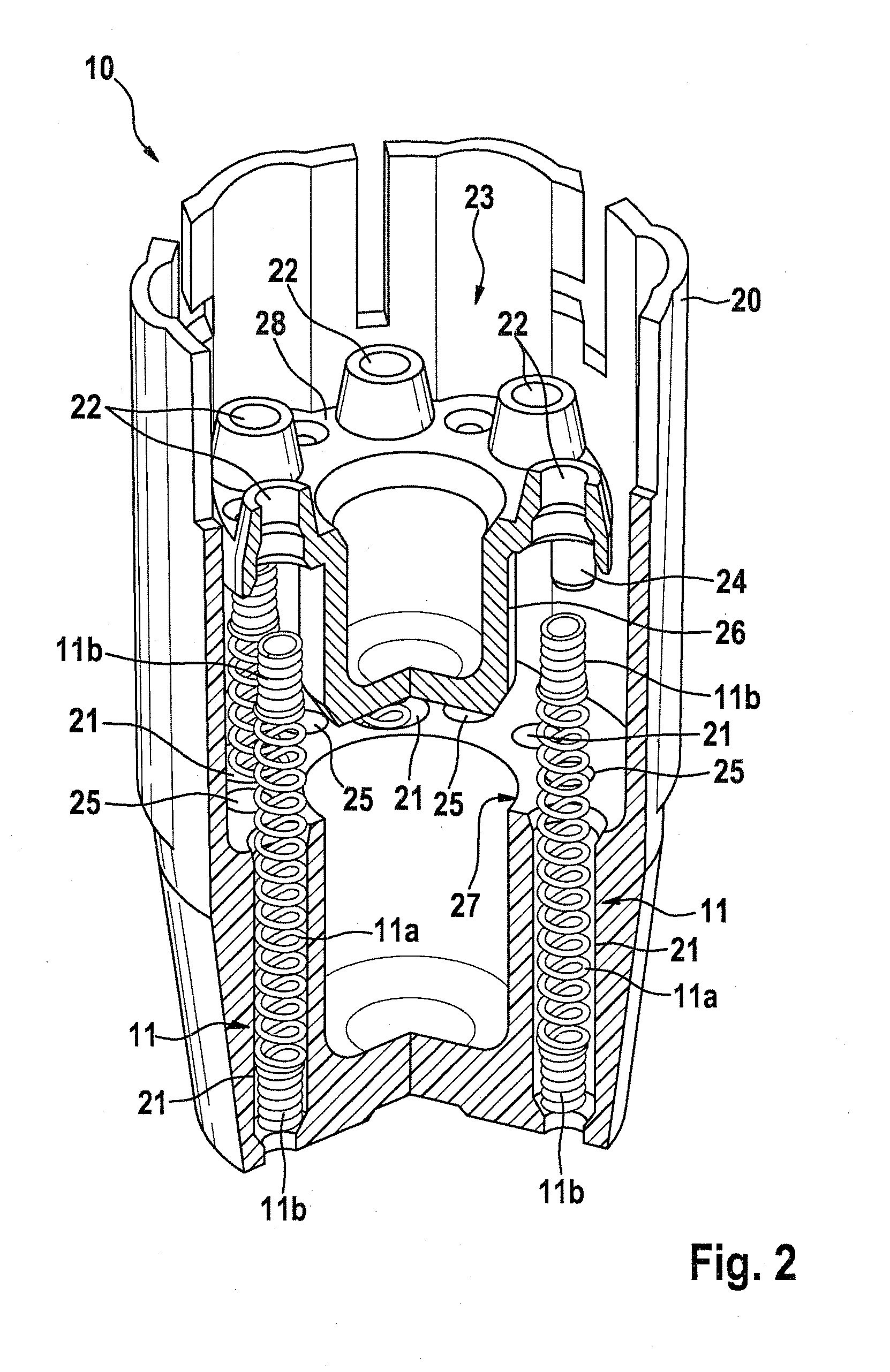
[0004]The pre-installation assembly according to the invention for a contact arrangement of a sensor assembly having the characteristics of independent claim 1 has the advantage over the prior art that a support component and a clamping component can be connected to one another in a simple way, via connection means, so that at least one spring contact pin is positioned and held in a simple way, via aligned guides, penetrated by the pin, in the support component and the clamping component. For forming the pre-installation assembly of the invention, the at least one spring contact pin is held in the guide of the support component, and a first end section of the at least one spring contact pin is axially braced in the associated guide of the support component. A second end section of the at least one spring contact pin is axially braced in the associated guide of the clamping component, and in the aligned position of the corresponding guides, the clamping component and the support component are connected to one another via the connection means. After the clamping component has been connected to the support component, the at least one spring contact pin is automatically compressed to the desired length and is kept in this position, captive, in the aligned guides of the clamping component and of the support component. As a result, advantageously, an easily manipulated pre-installation assembly for a contact arrangement of a sensor assembly is created.
[0006]It is especially advantageous that the aligned guides of the support component and of the clamping component, in order to be connected to one another, can easily be put into their construction position via positioning means of the corresponding support component and clamping component. As the connection means and / or positioning means between the clamping component and the support component, at least one press-fit peg, for instance, can be provided, which in the installed state is press-fitted into an associated press-fit bore. The press-fit peg and the associated press-fit bore can be structurally adapted to one another, for instance by means of a suitable predetermined shape, in such a way that in the installed state, a positionally correct connection between the clamping component and the support component is attainable. Alternatively, as the connection means and / or positioning means between the clamping component and the support component, a plurality of press-fit pegs and / or positioning pegs can be provided, which in the installed state are press-fitted into associated press-fit bores with a suitable pattern of holes. To facilitate the press-fitting operation in view of the relatively small dimensions of the individual components, a central press-fit peg can advantageously be provided as the connection means between the clamping component and support component; in the installed state, this peg is press-fitted into an associated press-fit bore, and as a the positioning means, a plurality of positioning pegs can be provided, which during the press-fitting operation are introduced into associated positioning bores with a suitable pattern of holes. The positioning pegs, which are smaller than the press-fit pegs, therefore serve the purpose of location positioning and therefore also serve as a protection against relative rotation.
[0010]To bring about simple axial bracing and simultaneously simple centering of the winding sections, forming the end regions, in the guide penetrated by them, the transition region of the spring contact pin can be wound conically, from its middle winding section to the winding section on the end regions that forms the tapered end region, with adaptation to a conical seat in the associated guide of the support component and clamping component, respectively. By means of a mirror-symmetrical design of the spring contact pin with respect to its central transverse axis, it can then be ensured that the spring contact pin can cooperate in both end regions with a conical seat, and as a result, the installation of the spring contact pin can be done more simply and in a way that is more secure against mistakes.
[0011]An especially simple design of the spring contact pin can be attained if the spring windings in the end regions of the spring contact pin of the invention are wound as a block for axial stiffening of these end regions. As a result, the spring contact pin can be a winding package wound in one piece of spring wire and can thus be produced economically as a mass-produced part in an optionally automated work cycle. Moreover, the radial bracing of the conical transition regions in the conical guide means can be improved by providing that the spring windings in the conical transition regions of the spring contact pin are at least predominantly, or entirely, also wound as a block. In contact-making for a sensor assembly or the like, the cost advantage is especially advantageous if the sensor assembly has a plurality of spring contact pins that are all designed structurally identically.

Problems solved by technology

As a result, producing the pre-installation assembly comprising the contact sleeve, contact spring and contact tappets is technically complicated as a whole, and even the individual spring contact pin comprising precision components is relatively expensive.
The space required for compressing the winding section is not structurally available in all contact arrangements for sensor assemblies.
Also, the contact face for the winding end of the shoulder winding section must be relatively large, which is again not wanted for every application, because it can have an adverse effect on the available space.

Method used


Image

  • Pre-installation assembly for a contact arrangement of a sensor assembly
  • Pre-installation assembly for a contact arrangement of a sensor assembly
  • Pre-installation assembly for a contact arrangement of a sensor assembly

Examples


Embodiment Construction

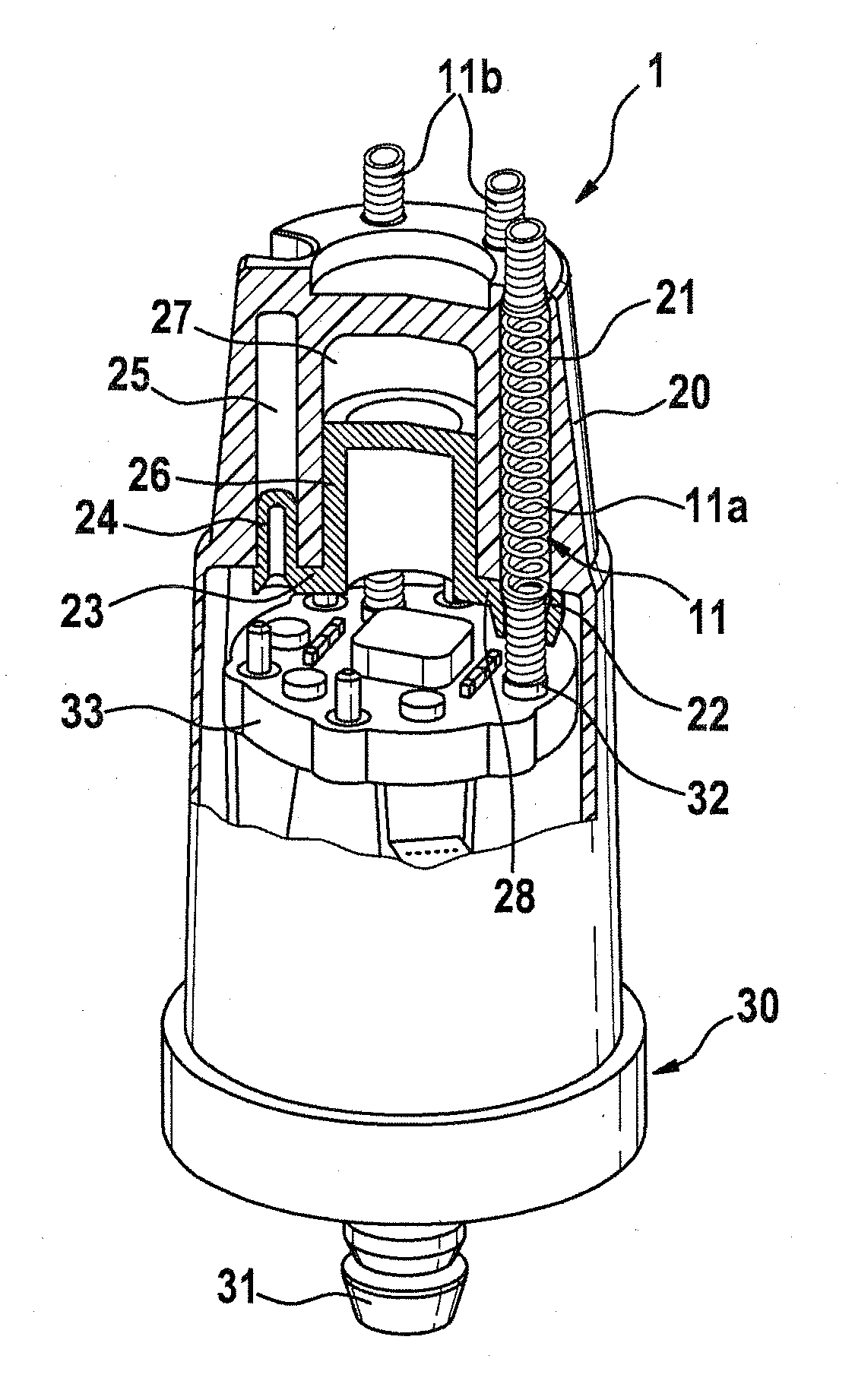
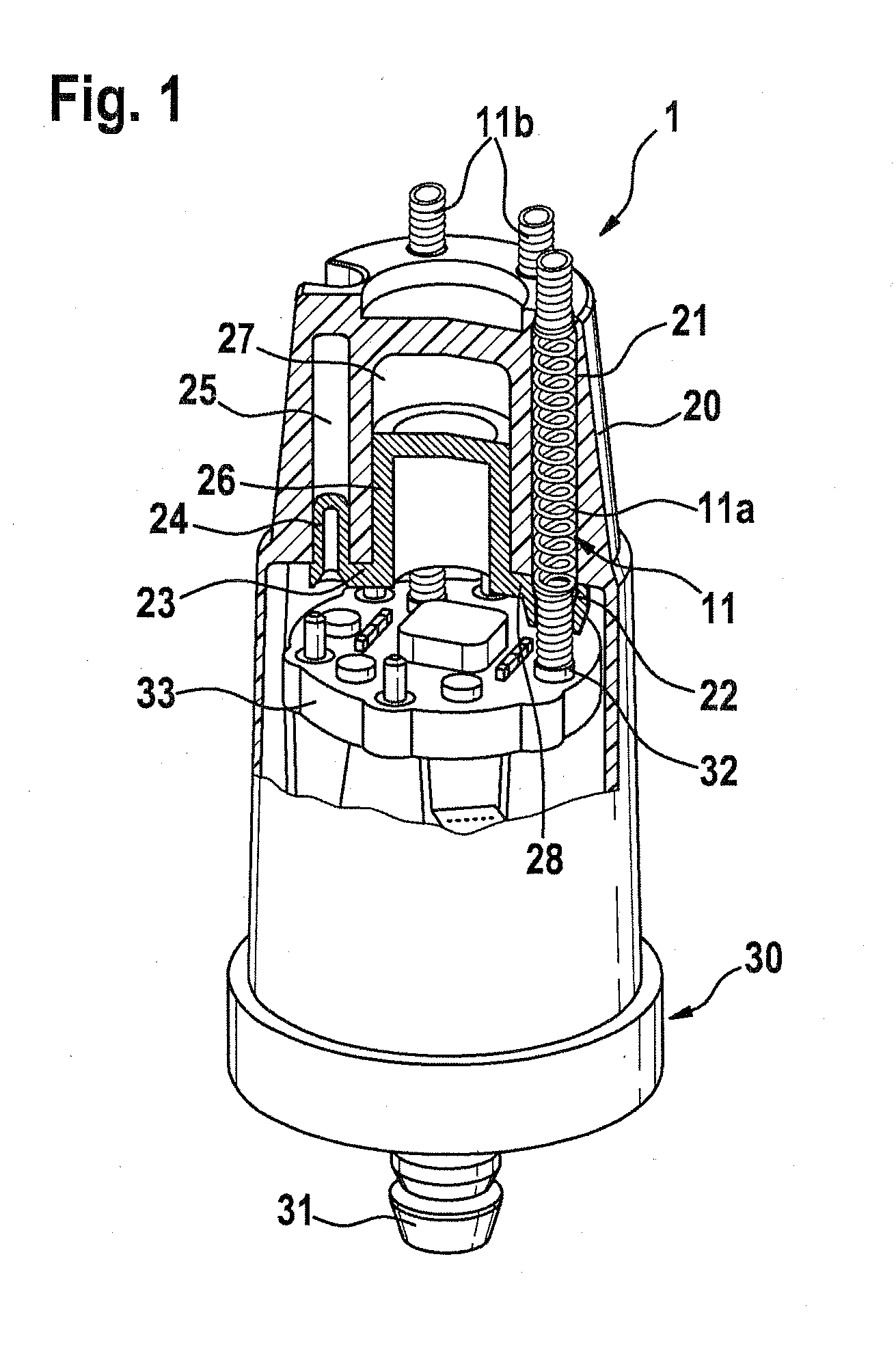
[0019]A contact arrangement 1 visible in FIG. 1 includes a total of four spring contact pins 11, which are disposed in a frustoconical housing capsule 20 of insulating plastic and serve the purpose of providing electrical contact for an attached control unit, not shown, for a braking device of a vehicle brake system with a pressure sensor of a sensor unit 30 for brake pressure measurement. Since the housing capsule 20 and the sensor unit 30 are shown broken open on a peripheral side, it is possible in FIG. 1 to see only three of the total of four spring contact pins 11. A tubular stub 31 protrudes from the underside of the sensor unit 30 and in the installed state engages an associated bore of a hydraulic block, not shown, thus providing sealing, and as a result, a fluidic communication of the pressure sensor with the hydraulic system of the associated brake system is established. In the assembled braking device, the contact arrangement 1 is thus located in such a way between the se...


PUM


Abstract

The invention relates to a pre-installation assembly for a contact arrangement of a sensor assembly, having a support component, a clamping component, and at least one spring contact pin. The conductive end areas of the at least one spring contact pin are connected with one another and are designed to be axially incompressible and held under an axial spring load between support surfaces that are at a distance from one another. According to the invention, the support component and the clamping component are connected with one another by way of a connection in which the at least one spring contact pin is positioned and held by way of aligned guides in the support component and in the clamping component, with the spring contact pin passing through the guides. In first end section of the at least one spring contact pin is axially supported in the associated guide of the support component, and a second end section of the at least one spring contact pin is axially supported in the associated guide of the clamping component.

Description

PRIOR ART[0001]The invention relates to a pre-installation assembly for a contact arrangement of a sensor assembly as generically defined by the preamble to independent claim 1.[0002]In German Published Patent Disclosure DE 19917941 A1, a braking device for a vehicle brake system with a contact arrangement for a sensor assembly is disclosed. In the braking device described, the control electronics, to simplify installation, are accommodated in a housing inverted over at least one pressure sensor, and the electrical connection between the pressure sensor and the control electronics is made automatically upon installation via four spring contact pins. In the process, the housing is secured to a hydraulic block of the braking device, into which block at least one pressure sensor is inserted, so that the spring contact pins are braced on their ends with a defined contact pressure between the facing contact faces of the pressure sensor and of the control electronics. The spring contact p...

Claims


Application Information

Patent Timeline
Patent Type & Authority Applications(United States)
IPC IPC(8): H02G15/02
CPCB60T8/3675H01R13/2421G01L19/143G01L19/0069
Inventor KAISER, HARRY
Owner ROBERT BOSCH GMBH
Learn More