Noise attenuator and resonator

a technology of attenuator and resonator, which is applied in the field of resonators, can solve the problems of mainly composed noise, overall sound level heard by the operator, and generation of noise which is transmitted to the operator's ear, and achieve the effect of reducing the noise radiated

Inactive Publication Date: 2011-05-12
DEERE & CO
View PDF34 Cites 10 Cited by
  • Summary
  • Abstract
  • Description
  • Claims
  • Application Information

AI Technical Summary

Benefits of technology

[0010]Accordingly, an object of this invention is to provide a compact system for attenuating noise generated by an engine air intake system.
[0012]These and other objects are achieved by the present invention, wherein a side branch resonator is affixed to an intake air conduit in the engine combustion air induction system. The resonator includes an outer pipe which extends from an open inlet to a closed end. One or more inner pipes are contained within the outer pipe. Each inner pipe shares a common open end with the outer pipe, but has its own closed end. The length of each pipe is determined by the desired frequency tuning of the resonator. The resonator acts to significantly reduce the noise radiated by the engine combustion air induction system.

Problems solved by technology

These pressure waves exit the intake air filter box, generating noise which is transmitted to the operator's ear.
This noise is a significant contributor to the overall sound level heard by the operator.
The resultant noise is comprised mainly of low frequency noise which is at a frequency that is too low to be attenuated by common techniques and methods such as acoustical foam.
Known conventional apparatus for attenuating multiple frequency sound waves are typically expensive and complex and are comprised of multiple component parts such as valves or flappers.
Such known devices for attenuating multiple frequencies are bulky and do not easily fit in the limited space of a refrigeration unit.

Method used


Image

  • Noise attenuator and resonator
  • Noise attenuator and resonator
  • Noise attenuator and resonator

Examples


Embodiment Construction

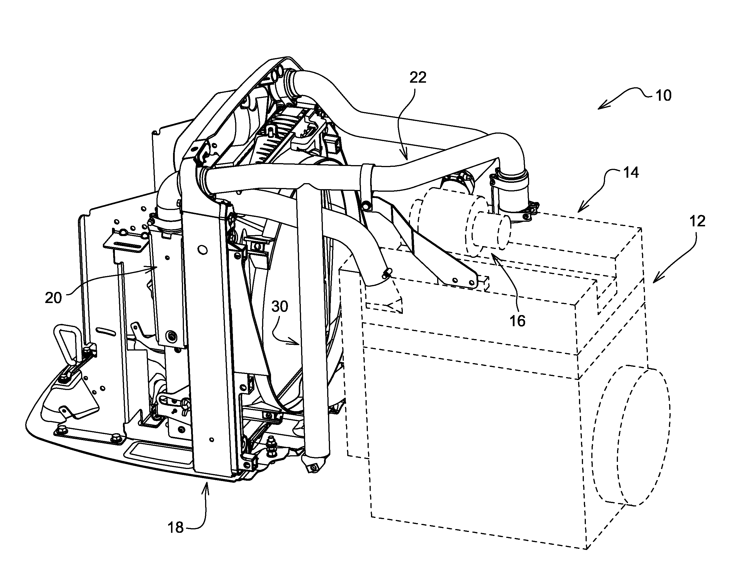
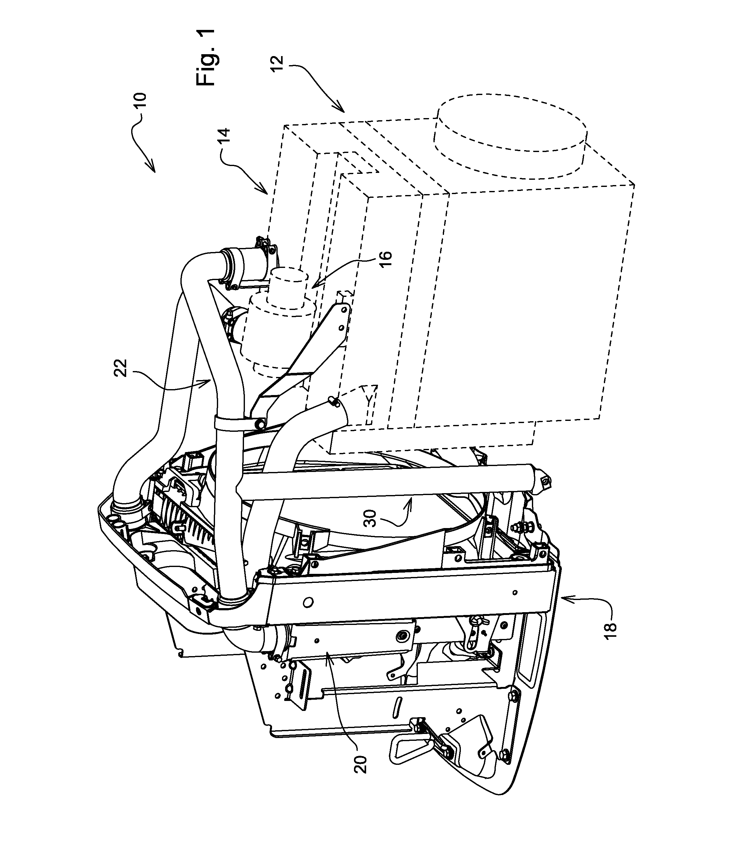
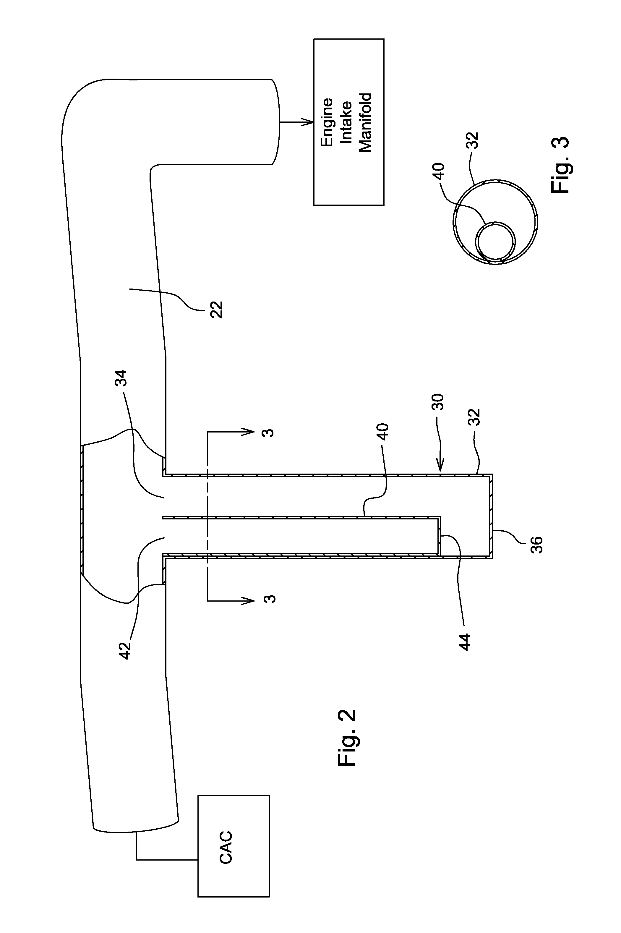
[0020]Referring to FIG. 1, a vehicle engine assembly 10 includes an engine 12 which has an intake manifold 14 and a turbo-compressor 16. Located in front of the engine 12 is a radiator 18 and a charge air cooler 20. A conduit 22 communicates cooled intake charge air from the charge air cooler 20 to the intake manifold 14.

[0021]A noise attenuator 30 is connected to a mid portion of the conduit 22. As best seen in FIGS. 2 and 3, the noise attenuator 30 includes a first or outer cylindrical tube 32 with an open end 34 and a closed end 36. A second or inner cylindrical tube 40 is received within the outer tube 32. A wall of inner tube 40 engages an inner surface of a wall of outer tube 32. Inner tube 40 has an open end 42 and a closed end 44, and is shorter than outer tube 32. The diameter and lengths of tubes 32 and 40 are chosen so as to attenuate noise at two different desired noise frequencies.

[0022]The inner tube 40 is preferably welded to the outer tube 32 using a few plug welds (...


PUM


Abstract

A resonator attenuates sound waves at first and second frequencies. The resonator includes a first tube, and a second tube received within the first tube. Both tubes have an open end and a closed end. The first tube has an axial length which is longer than the axial length of the second tube. The first tube attenuates sound waves at the first frequency and the second tube attenuates sound waves at the second frequency. The second tube has an outer wall which engages an inner wall of the first tube. The open end of the second tube is surrounded by the open end of the first tube. The open end of the first tube is attached to an engine air intake conduit. The conduit communicates air from a charge air cooler to an engine intake manifold.

Description

FIELD OF THE INVENTION[0001]The present invention relates to a resonator for reducing noise generated by the air intake system of an internal combustion engine.BACKGROUND OF THE INVENTION[0002]The operation of a vehicle engine causes pressure waves to propagate through the air induction system. These pressure waves exit the intake air filter box, generating noise which is transmitted to the operator's ear. This noise is a significant contributor to the overall sound level heard by the operator. The resultant noise is comprised mainly of low frequency noise which is at a frequency that is too low to be attenuated by common techniques and methods such as acoustical foam.[0003]A number prior art attempts have been made to reduce such noise generated by a combustion engine used in automotive and other applications. Existing devices which have capability to attenuate multiple frequencies utilize multiple, separate resonator tubes, multiple tubes connected to a common inlet, or single tub...

Claims


Application Information

Patent Timeline
Patent Type & Authority Applications(United States)
IPC IPC(8): F02M35/12
CPCF02M35/1266
Inventor EDGINGTON, JASON MICHAELBUERKLE, BRYAN KIRKGIRARD, JEFFREY JOHNBROWN, JEFFERY KAHLE
Owner DEERE & CO
Why Eureka
Try Eureka