Exhaust system hanger of vehicle

a technology of exhaust system and hanger, which is applied in the direction of machine supports, machines/engines, other domestic objects, etc., can solve the problems of not being able to appropriately deal with the large vibration, unable to absorb unable to absorb both the small vibration and the large vibration of the exhaust system, so as to achieve excellent nvh performance of the vehicle and effectively absorb the small vibration

Active Publication Date: 2011-05-12
HYUNDAI MOTOR CO LTD
View PDF3 Cites 6 Cited by
  • Summary
  • Abstract
  • Description
  • Claims
  • Application Information

AI Technical Summary

Benefits of technology

[0012]Various aspects of the present invention are directed to provide an exhaust system hanger of a vehicle that makes it possible to achieve excellent NVH performance of the vehicle by effectively absorbing small vibration generated when the vehicle travels, without a specific additional component, and keeps the exhaust system stable by appropriately restricting the maximum motion of the exhaust system due to large vibration generated by abrupt changes in motion of the vehicle.
[0025]An exhaust system hanger of a vehicle according to the present invention makes it possible to achieve excellent NVH performance of the vehicle by effectively absorbing small vibration generated when the vehicle travels, without a specific additional component, and keeps the exhaust system stable by appropriately restricting the maximum motion of the exhaust system due to large vibration generated by abrupt changes in motion of the vehicle.

Problems solved by technology

The vibration of the exhaust system can fall into a small vibration generated by combustion in the engine when the vehicle is in travel and large vibration caused by rapid stop or start of the vehicle.
Hangers generally used in the related art, however, cannot absorb both of the small vibration and the large vibration of the exhaust system, such that they cannot appropriately deal with the large vibration when being configured to absorb the small vibration of the exhaust system, and on the contrary, cannot absorb the small vibration when being configured to absorb the large vibration of the exhaust system.
Accordingly, they reduce NVH performance of vehicles.
However, adding the band to the hanger causes new problems, such as that the work processes and manufacturing cost increase.

Method used


Image

  • Exhaust system hanger of vehicle
  • Exhaust system hanger of vehicle
  • Exhaust system hanger of vehicle

Examples


first embodiment

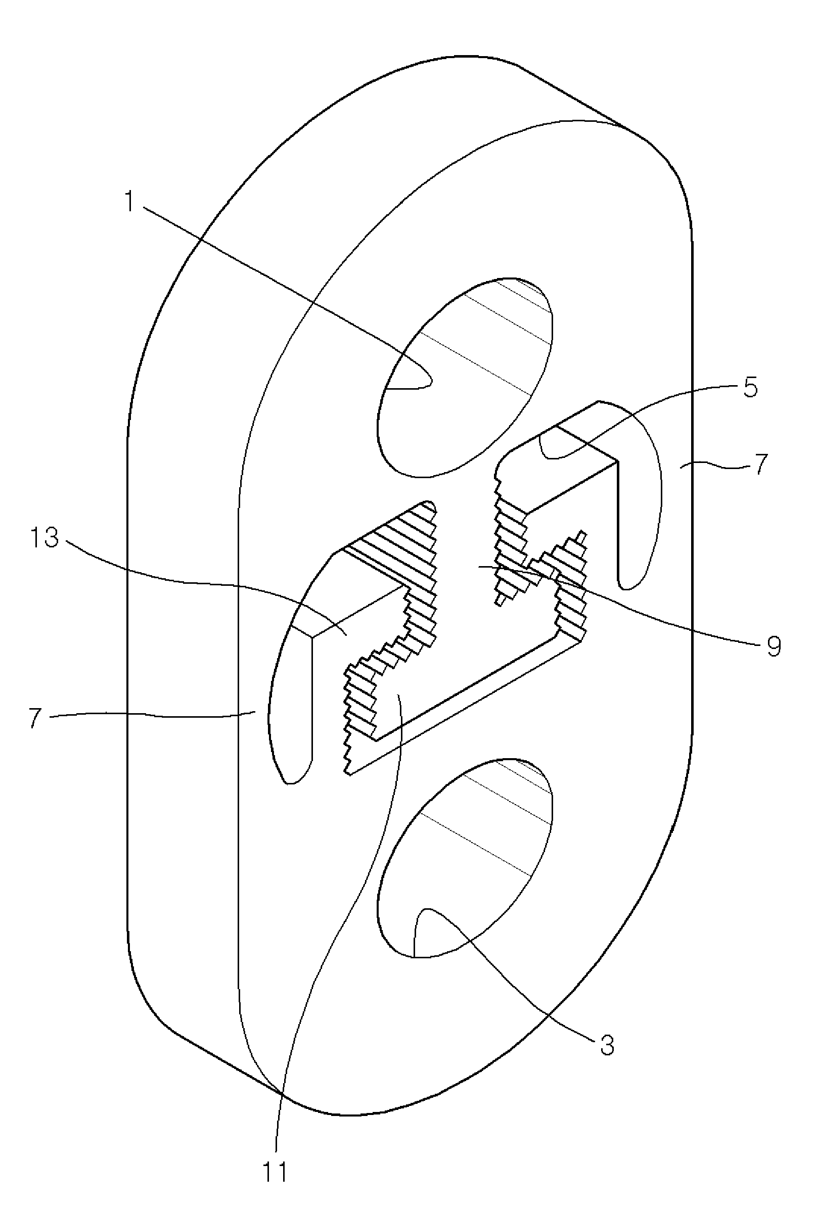
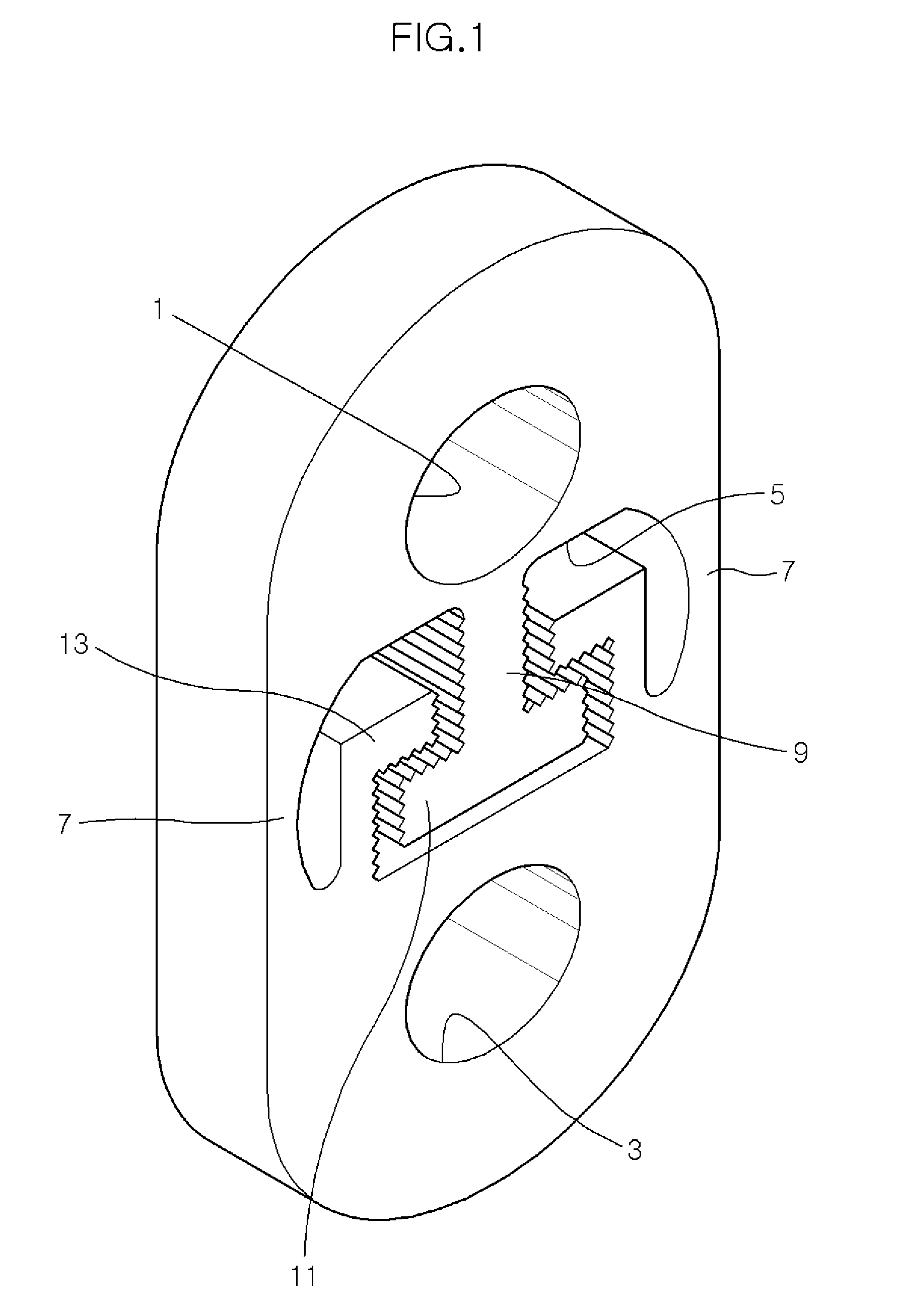
[0033]An exhaust system hanger according to the present invention is shown in FIGS. 1 and 2.

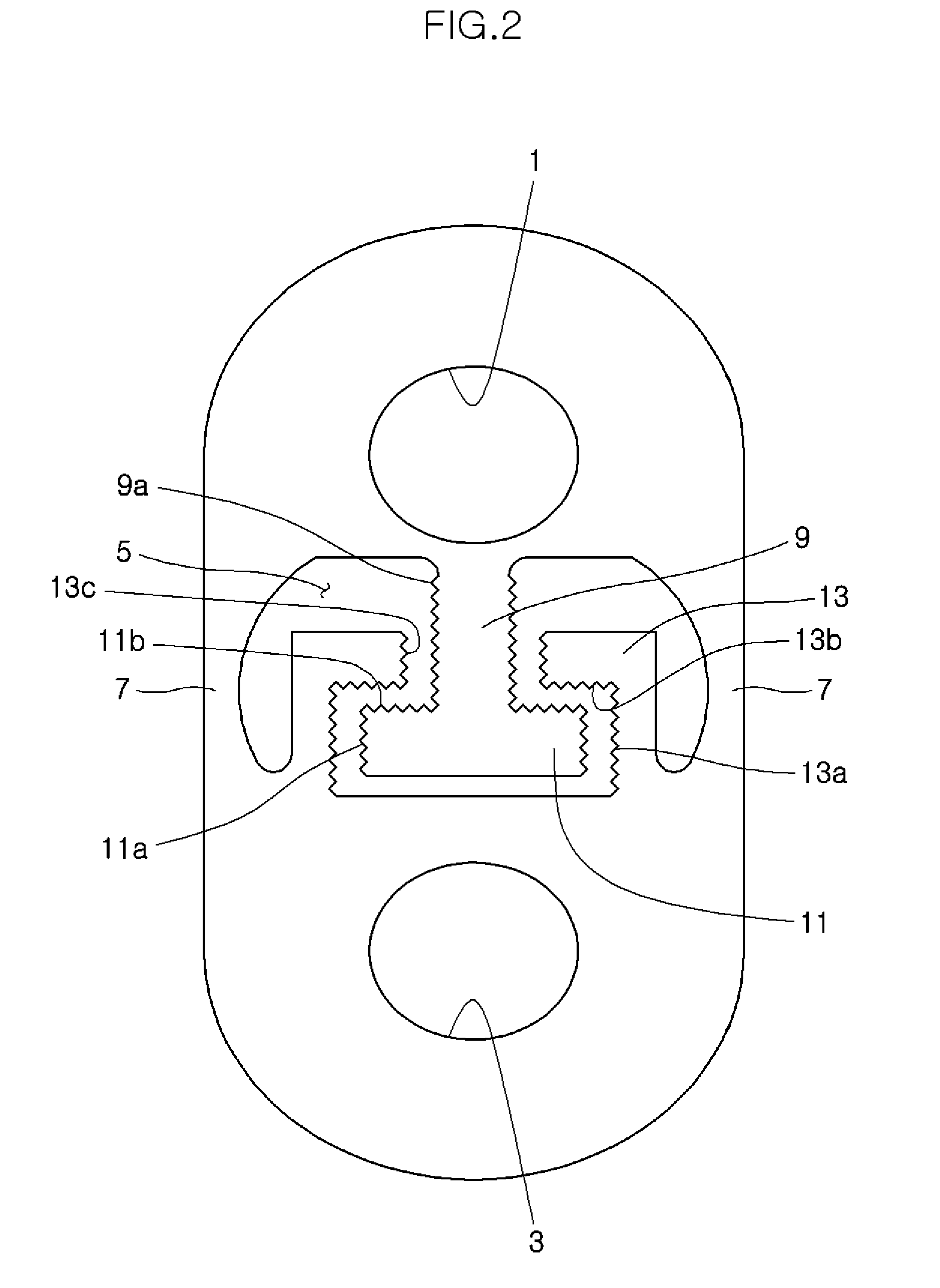
[0034]As shown in the figures, a hanger according to a first embodiment of the present invention has connection holes 1 and 3 formed at both end portions to be connected with the car body and the exhaust system, a mid-hole 5 formed between the connection holes 1 and 3, and bridges 7 with both ends connected to both sides of mid-hole 5.

[0035]A column 9 protruding from an upper surface of the mid-hole 5 toward the second connection hole 3 is formed in the mid-hole 5 and wing 11 protruding toward bridges 7 is formed at both sides of the distal end of column 9.

[0036]Further, locking portions 13 protruding from a lower surface of the mid-hole 5 toward first connection hole 1 and covering the upper surface 11b and a lateral side 11a of wing 11 is formed in mid-hole 5.

[0037]That is, column 9 and wings 11 make an inverse T-shape and locking portions 13 covering both wings 11 at their sides are formed...

second embodiment

[0053]FIG. 3 shows a hanger according to the present invention, which is different from the hanger shown in FIG. 2 in that the lateral side 11a and the upper inclined surface 11b of wing 11 are flat and the lower lateral sides 13a and the lower inclined surfaces 13b of locking portions 13 are flat in parallel with lateral side 11a and upper inclined surface 11b of wings 11, respectively. In particular, upper inclined surface 11b of wing 11 inclines toward lower inclined surfaces 13b of locking portions 13, and lower inclined surfaces 13b of locking portion 13 which face upper inclined surface 11b of wing 11 declines in parallel with upper inclined surface 11b of wing 11.

[0054]Therefore, upper inclined surface 11b of wing 11 contacts with lower inclined surfaces 13b of locking portions 13 in large vibration of the exhaust system and friction force therebetween considerably increases, such that the hanger according to the second embodiment of the present invention can effectively rest...

third embodiment

[0055]FIG. 4 shows a hanger according to the present invention, which is different from the hanger shown in FIG. 3 in that the lateral side 11a and the upper inclined surface 11b of wing 11 are indented, and the corresponding lower lateral sides 13a and the lower inclined surfaces 13b of locking portions 13 are also indented.

[0056]Further, both lateral sides 9a of column 9 are also indented and the upper lateral sides 13c of locking portions 13 which face both lateral sides 9a of column 9 are also indented.

[0057]Upper inclined surface 11b of wing 11 and lower inclined surfaces 13b of locking portion 13 incline and decline, which is the same as the hanger shown in FIG. 3.

[0058]Therefore, as in the hanger shown in FIG. 2, since both lateral sides 11a and lower lateral sides 13a are engaged and upper inclined surface 11b and lower inclined surfaces 13b are engaged while both lateral sides 9a of column 9 and upper lateral sides 13c of locking portions 13 are engaged, friction forces bet...


PUM


Abstract

The present invention relates to an exhaust system hanger of a vehicle, in which two protrusions facing and spaced apart from each other are integrally formed at a center portion between both distal ends of the hanger, and the two protrusions selectively contact each other to increase a spring constant, when the shape of the hanger is elastically deformed by external force beyond a predetermined elastic value.

Description

CROSS-REFERENCE TO RELATED APPLICATIONS[0001]The present application claims priority to Korean Patent Application Number 10-2009-0107929 filed Nov. 10, 2009, the entire contents of which application is incorporated herein for all purposes by this reference.BACKGROUND OF THE INVENTION[0002]1. Field of the Invention[0003]The present invention relates to an exhaust system hanger of a vehicle, in more detail the structure of a hanger supporting the muffler etc at the lower portion of a vehicle.[0004]2. Description of Related Art[0005]In general, the exhaust system of vehicles includes a muffler depressurizing high-temperature and high-pressure gas discharged from the engine to reduce noise and a catalytic converter purifying the exhaust gas, and is fixed by hangers at a plurality of positions at the lower portion of the car body.[0006]The hangers are made of a material capable of providing elasticity, such as rubber, and of which one end is connected to the car body and the other end is...

Claims


Application Information

Patent Timeline
Patent Type & Authority Applications(United States)
IPC IPC(8): F16L3/00
CPCB60K13/04F16L55/035F01N13/1811F01N13/08F01N13/00
Inventor PARK, KICHUL
Owner HYUNDAI MOTOR CO LTD
Why Eureka
Try Eureka