Rotary electrical machine

Active Publication Date: 2011-05-12
HITACHI LTD +1
View PDF55 Cites 59 Cited by
  • Summary
  • Abstract
  • Description
  • Claims
  • Application Information

AI Technical Summary

Benefits of technology

[0018]As an embodiment of the present invention makes it possible to reduce magnetic flux leakage, the s

Problems solved by technology

When a conventional technology is employed, it is difficult to manufacture a magnet row because magnets are disposed in such a manner that N-poles face each other whi

Method used


Image

  • Rotary electrical machine
  • Rotary electrical machine
  • Rotary electrical machine

Examples


Embodiment Construction

[0041]Embodiments of the present invention will now be described.

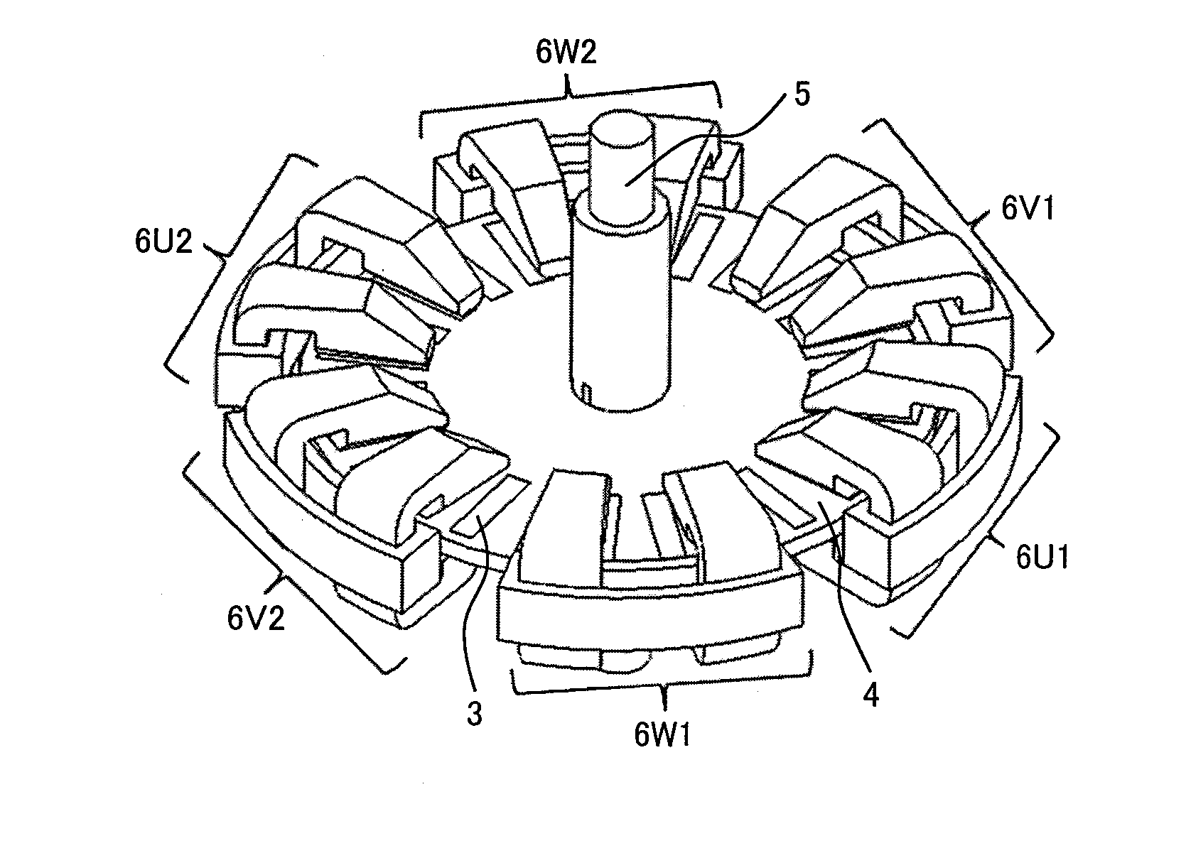
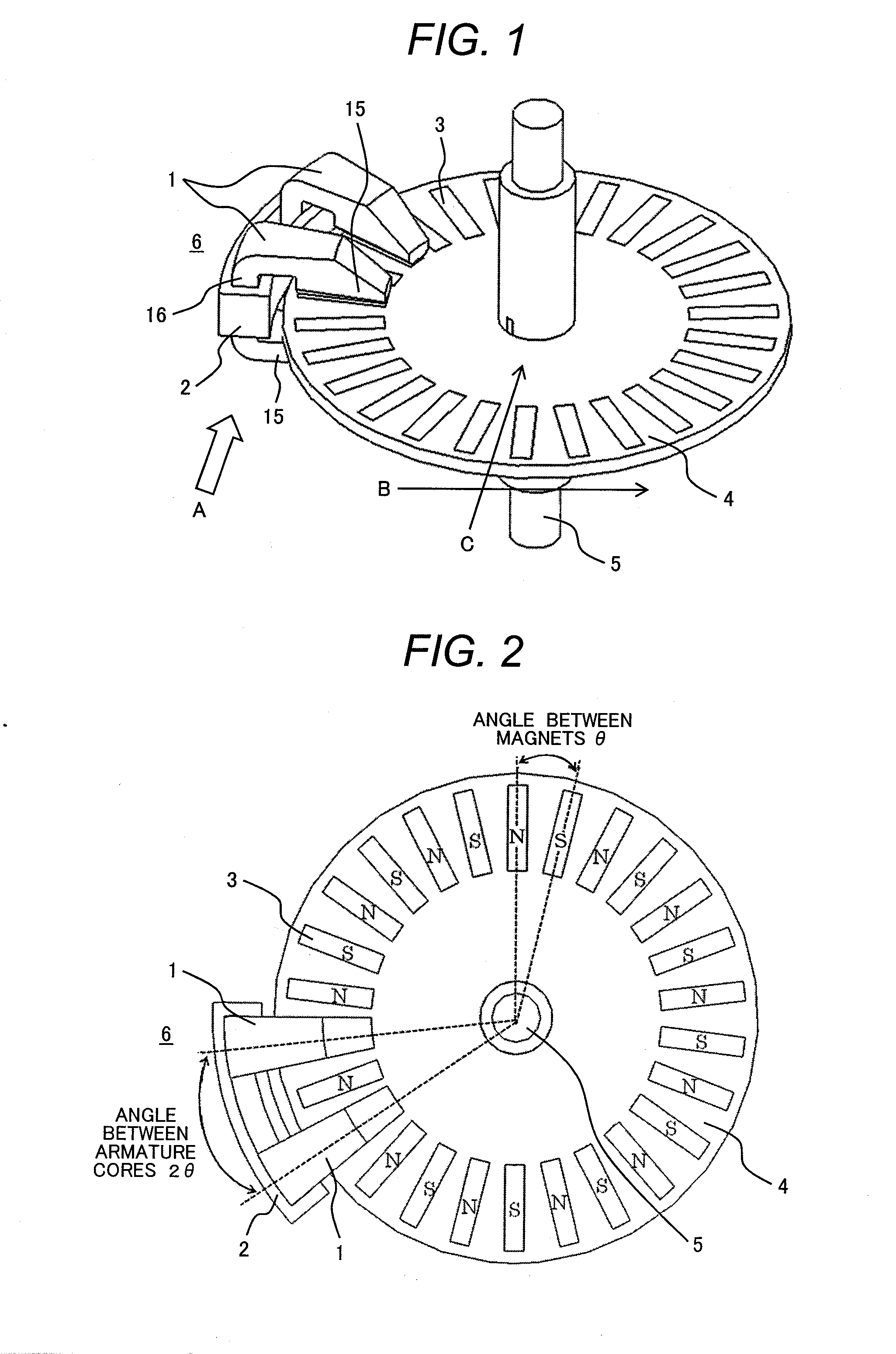
[0042]FIG. 1 shows an example basic configuration of a rotary electrical machine according to an embodiment of the present invention. The rotary electrical machine shown in FIG. 1 includes a shaft 5, a disc-shaped rotor 4 whose center is fastened to the shaft 5, and an armature 6 configured to sandwich the disc-shaped rotor 4. Plural magnets 3 are mounted on the periphery of the disc-shaped rotor 4. The armature 6 includes plural armature cores 1, which are disposed to sandwich the magnets 3 mounted on the periphery of the disc-shaped rotor 4, and a winding 2, which is commonly provided for the armature cores 1. When the armature 6 is viewed in the direction of arrow A in FIG. 1, each of the armature cores 1 is obviously shaped like the letter C, and includes a core portion 16 that joins a magnetic pole tooth 15 above the front surface of the rotor 4 and a magnetic pole tooth 15 beneath the back surface of the rotor 4 ...


PUM


Abstract

When a conventional technology is employed, it is difficult to manufacture a magnet row because magnets are disposed so that N-poles face each other while S-poles face each other. Further, magnetic reluctance is increased because a generated magnetic flux obliquely crosses an air gap in which the magnets are disposed. Furthermore, the conventional technology is at a disadvantage in that magnetic flux interference occurs between neighboring magnetic poles. The present invention has been made to address the above problems and provide a rotary electrical machine capable of generating high torque at low speed. The rotary electrical machine includes a rotor disc and an armature. The rotor disc is configured so that plural rectangular magnets whose longitudinal direction crosses the direction of rotor disc rotation are disposed on the rotor disc, and that the polarities of neighboring magnets differ from each other. The armature is configured so that plural armature cores are disposed to sandwich the magnets, which are mounted on the rotor disc and provided with a particular magnetic pole, and that a winding is commonly wound between the armature cores.

Description

CLAIM OF PRIORITY[0001]The present application claims priority from Japanese Patent application serial no. 2009-255821, filed on Nov. 9, 2009, the content of which is hereby incorporated by reference into this application.FIELD OF THE INVENTION[0002]The present invention relates to a rotary electrical machine that decreases the spacing interval between neighboring magnetic poles, provides low-speed, high-torque drive, and reduces torque ripple.BACKGROUND OF THE INVENTION[0003]In a conventional rotary electrical machine having a sandwiched rotor, magnets are disposed in such a manner that N-poles face each other while S-poles face each other, as described in JP-A No. 117116 / 1997. Further, the magnets face each other while they are sandwiched between stator cores. A spiral magnetic flux is generated in a magnetic circuit including a stator core so that oblique magnetic flux linkage occurs in relation to a magnet.[0004]When a conventional technology is employed, it is difficult to manu...

Claims


Application Information

Patent Timeline
IPC IPC(8): H02K1/12
CPCH02K1/141H02K21/24H02K1/145H02K2201/15
Inventor AOYAMA, YASUAKIKOSEKI, TAKAFUMI
Owner HITACHI LTD
Why Eureka
Try Eureka