Vibration power generator, vibration power generating device and communication device having vibration power generating device mounted thereon

a technology of vibration power generator and vibration power generating device, which is applied in the direction of generator/motor, influence generator, electrical apparatus, etc., can solve the problems that the static induction vibration power generator b>100/b> is incapable of extracting external vibrations in the direction other than the direction of the x-axis as electrical energy, and achieves stable output voltage, high output, and low cost

Active Publication Date: 2011-05-12
PANASONIC CORP
View PDF13 Cites 12 Cited by
  • Summary
  • Abstract
  • Description
  • Claims
  • Application Information

AI Technical Summary

Benefits of technology

[0042]In accordance with the vibration power generator of the present invention, one of the two electrodes facing each other receives an externally-applied force to vibrate in the direction of the X-axis and the direction perpendicular to the X axis (the direction of the Y-axis), and it is possible to convert the vibration into electric power without decreasing the electrical generating efficiency. Further, the vibration power generating device of the present invention includes the vibration power generator of the present invention, that is capable of supplying electric power at a relatively high output. Moreover, in the case where the vibration power generating device of the present invention includes an electric storage circuit, it is possible to stabilize an output voltage. It is possible for the vibration power generator of the present invention to function as a power source for a communication device. Since the vibration power generating device of the present invention is capable of performing electrical generation by an externally-applied force (for example, a force applied when a person is walking, a vibration applied when driving a car, or the like), the communication device using the vibration power generating device of the present invention is capable of reducing the number of maintenances such as battery exchanges, which is advantageous in view of resource saving and environmental protection.

Problems solved by technology

Therefore, this static induction vibration power generator 100 is incapable of extracting external vibrations in the directions other than the direction of the X-axis as electrical energy.

Method used


Image

  • Vibration power generator, vibration power generating device and communication device having vibration power generating device mounted thereon
  • Vibration power generator, vibration power generating device and communication device having vibration power generating device mounted thereon
  • Vibration power generator, vibration power generating device and communication device having vibration power generating device mounted thereon

Examples


first embodiment

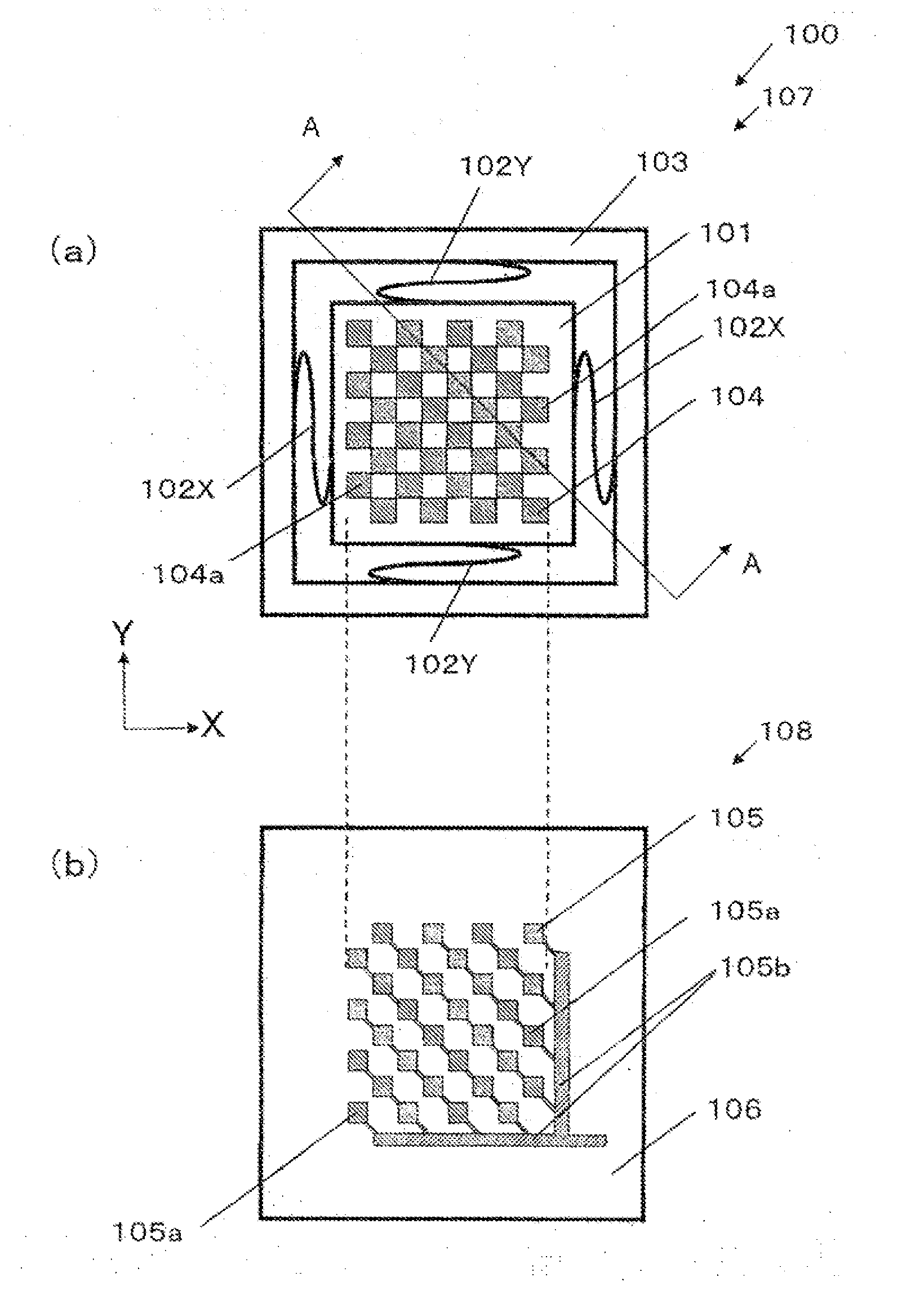
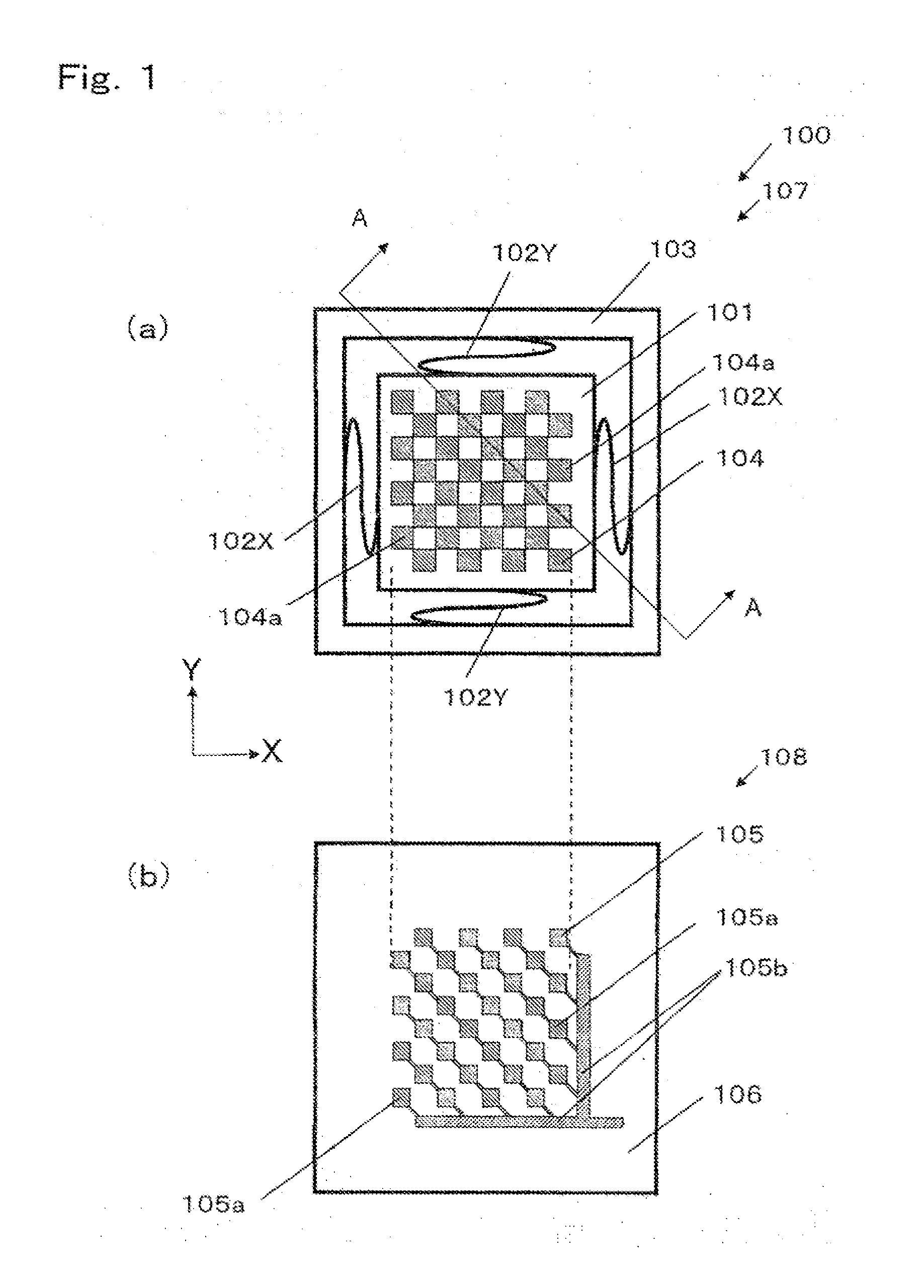
[0059]FIG. 1 shows a vibration power generator according to a first embodiment of the present invention. FIG. 1(a) is a top view of a vibration power generator 100, and FIG. 1(b) is a top view of a second structure 108 including a second substrate 106 on which a second electrode 105 is formed. Meanwhile, in FIG. 1(a), a first electrode 104 formed on a first substrate 101 is shown in order to facilitate understanding. In the actual vibration power generator, the first electrode and the second electrode face each other, and those are therefore not shown in appearance.

[0060]The vibration power generator 100 is composed of a first structure 107 and the second structure 108. The first structure 107 includes the first substrate 101 and a fixation structure 103, and the first electrode 104 is formed on the first substrate 101. The first substrate 101 is connected to the fixation structure 103 with elastic structures 102X and 102Y, and is capable of vibrating in the direction of the X-axis ...

second embodiment

[0096]FIG. 6 shows a top view of a vibration power generator 400 according to a second embodiment of the present invention, a cross-sectional view taken along the line A-A, and a cross-sectional view taken along the line B-B. The present embodiment is different from the first embodiment in the point that a spring constant in the direction of the X-axis of an elastic structures 402 that causes the first substrate to vibrate in the direction of the X-axis is different from a spring constant in the direction of the Y-axis of an elastic structure 402Y that causes the first substrate to vibrate in the direction of the Y-axis. In order to conceptually show a difference between the spring constants, the illustration is made such that the number of springs as the elastic structure 402X is different from the number of springs as the elastic structure 402Y. The elastic structure(s) is not necessarily springs, and may be formed of an elastomer material, or may be formed by processing onto a se...

third embodiment

[0112]FIG. 8 is a top view of a first structure 707 of a vibration power generator 700 according to a third embodiment of the present invention.

[0113]Similarly to FIG. 1, in FIG. 8 as well, a first electrode 704 formed on the first structure 707 is shown for easy understanding. In the actual vibration power generator, the first electrode 704 is disposed on the bottom surface of the first substrate to face a second electrode, and those are therefore not shown in appearance.

[0114]In FIG. 8, the description of the second structure used for the vibration power generator 700 is omitted. As the second structure of the vibration power generator 700, for example, any one of the second structures shown in the present specification including a structure with the same configuration of the second structure 108 of the vibration power generator 100 shown in FIG. 1 may be used.

[0115]The present embodiment is different from the first embodiment in the point that a variable structure 705 is provided...


PUM


Abstract

Generating efficiency of a vibration power generating device, which generates power by vibration in the biaxial direction, is improved. The vibration power generating device is provided with: a first substrate (101) and a second substrate (106); a first electrode (104) formed on the first substrate; a fixed structural body (103); elastic structural bodies (102X, 102Y) which connect the first substrate and the fixed structural body with each other; and a second electrode (105) formed on the second substrate. Since the overlapping area of the electrodes is increased by arranging rectangular or square conductor parts (104a) of the first electrode and rectangular or square conductor parts (105a) of the second electrode in a checkerboard pattern, a generation region where power is generated by vibration is increased.

Description

TECHNICAL FIELD[0001]The present invention relates to a vibration power generator, a vibration power generating device, and a communication device having the vibration power generating device mounted thereon. In particular, the present invention relates to a static induction vibration power generator using an electret, a vibration power generating device, and a communication device having the vibration power generating device mounted thereon.BACKGROUND ART[0002]A static induction vibration power generating device in which electric charges are provided to one electrode of a variable capacitance, and the electrode charges are induced to the opposed electrode by a static induction, a change in the induced electric charges is brought about by a change in capacitance, and the change in the electric charges is extracted as electrical energy, has been already proposed (refer to, for example, Patent document 1 shown below).[0003]FIG. 14 shows a static induction vibration power generator des...

Claims


Application Information

Patent Timeline
Patent Type & Authority Applications(United States)
IPC IPC(8): H02N1/08
CPCH02N1/08
Inventor NAKATSUKA, HIROSHIONISHI, KEIJINOMURA, KOJI
Owner PANASONIC CORP
Why Eureka
Try Eureka