Method and system for co-operative charging of electric vehicles

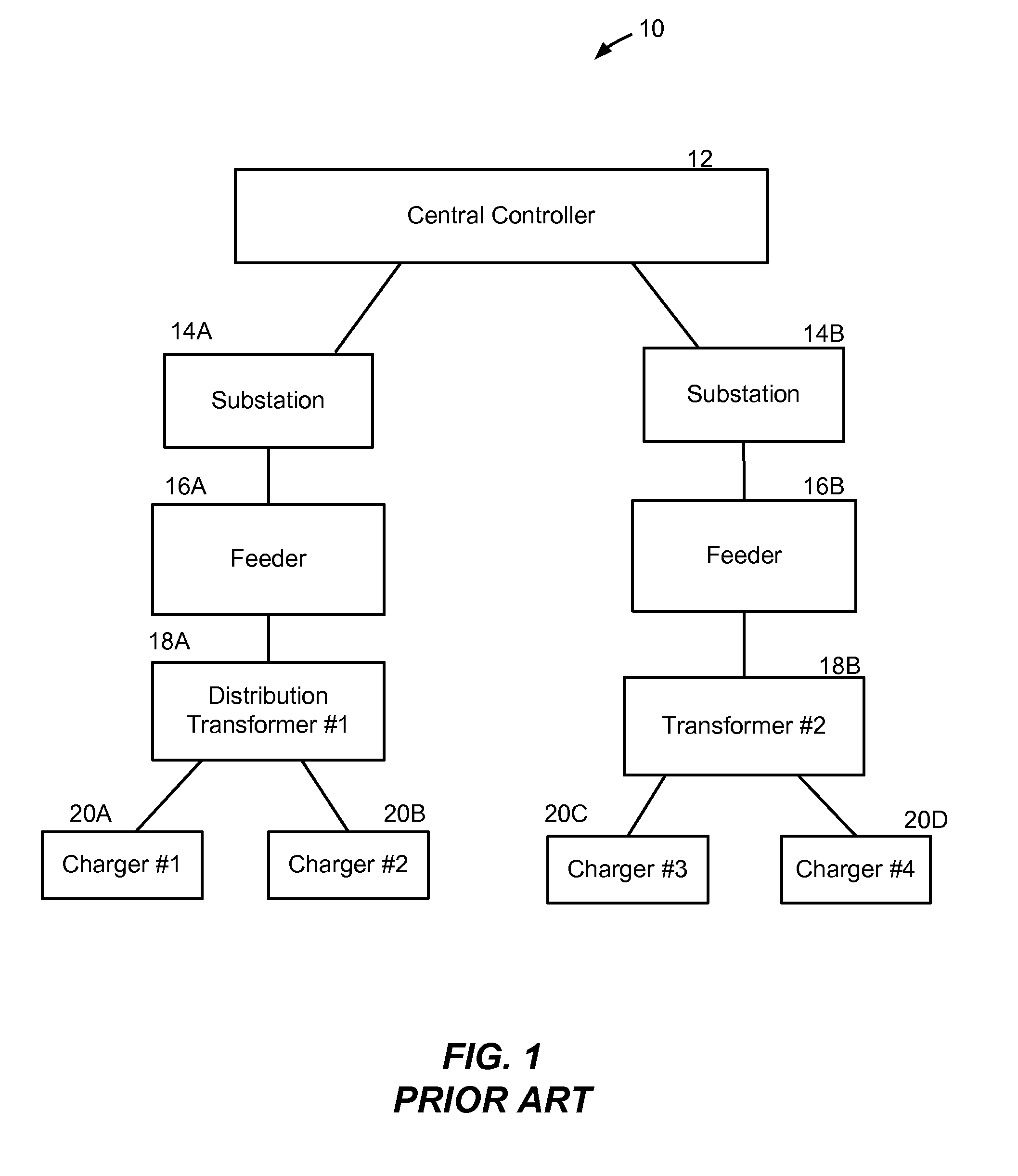
a technology of electric vehicles and charging methods, applied in the direction of electrochemical generators, capacitors, electric devices, etc., can solve the problems that the charger coupled to a first transformer will likely not be able to detect or communicate with other chargers who are coupled to a second transformer, so as to prevent overloading and avoid possible failure of a distribution transformer

Active Publication Date: 2011-05-12
ITRON
View PDF10 Cites 85 Cited by
  • Summary
  • Abstract
  • Description
  • Claims
  • Application Information

AI Technical Summary

Benefits of technology

Only chargers with a token may receive energy from the distribution transformer. In this way, a distribution transformer is not overloaded by energy requests and trying to fulfill those ener...

Problems solved by technology

In other words, chargers coupled to a first transformer will likely not be able to detect or communicate with other chargers who are coupled to a second tra...

Method used


Image

  • Method and system for co-operative charging of electric vehicles
  • Method and system for co-operative charging of electric vehicles
  • Method and system for co-operative charging of electric vehicles

Examples


Embodiment Construction

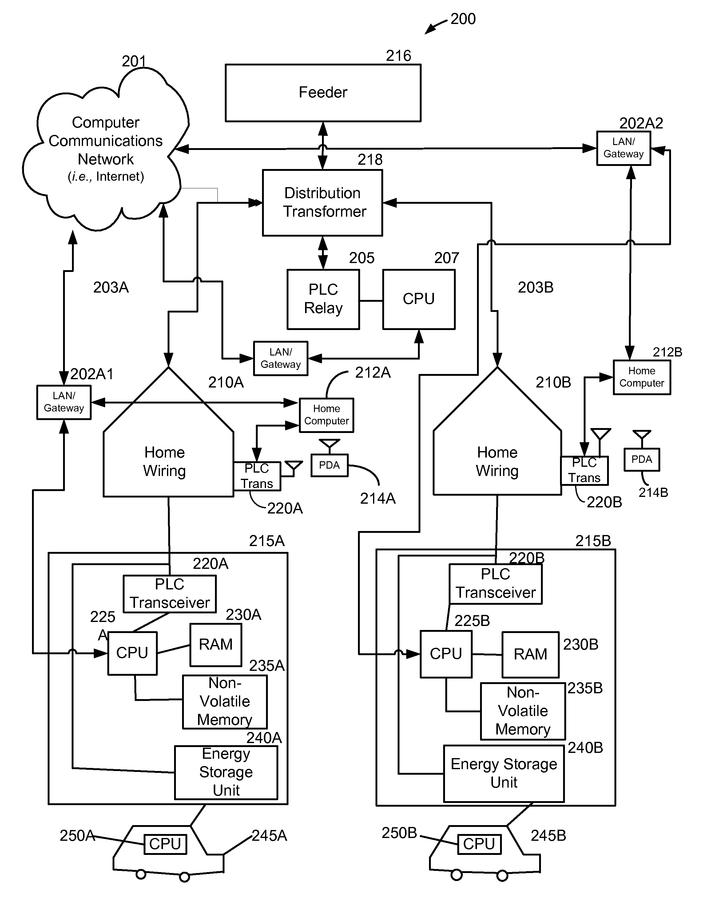
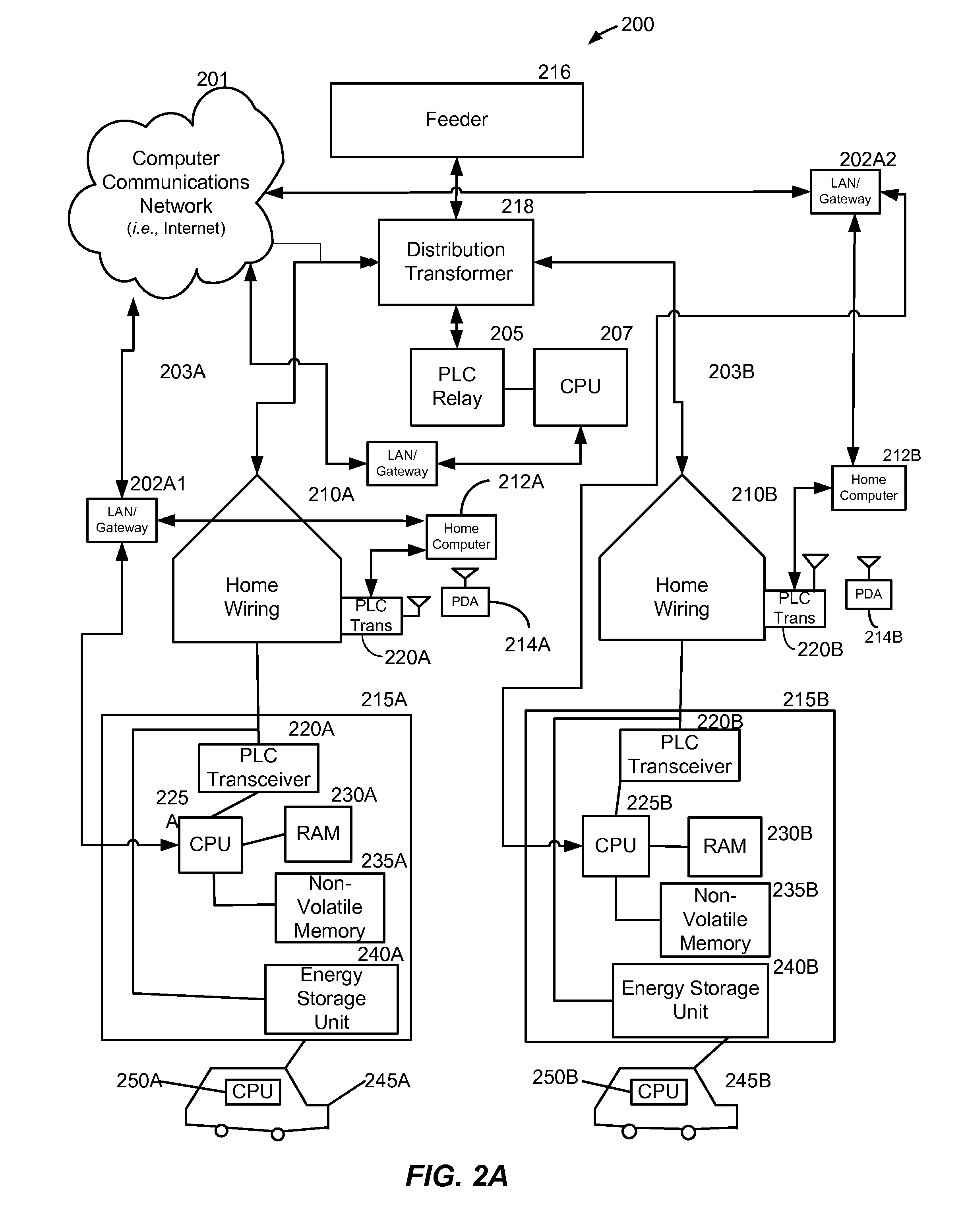
A method and system provide for the cooperative and coordinated charging and discharging of electric vehicles. By using power line communications, chargers of the electric vehicles who are serviced by the same distribution transformer can form self-contained local area networks due to the nature of power line communications. After the chargers of the electric vehicles are coupled to one another through power line communications, they can form a token ring network. According to this token ring network, a predetermined number of tokens can be assigned within the token ring network for permitting chargers with tokens to charge respective electric vehicles while chargers without tokens must wait until they receive a token to initiate charging. By limiting the number of vehicles who are charging simultaneously, the load on a particular transformer which services several vehicles (households) is restricted to safe levels.

Turning now to the drawings, in which like reference numerals refer ...


PUM


Abstract

A method and system provide for the cooperative charging of electric vehicles. By using power line communications, chargers of the electric vehicles who are serviced by the same distribution transformer can form self-contained local area networks due to the nature of power line communications (PLCs). Alternatively, or in addition to the PLCs, other communication networks, such as the Internet and local area networks, may be used as part of the communications infrastructure for the chargers. After the chargers of the electric vehicles are coupled to one another through power line communications or traditional communications networks, they can form a logical token ring network. According to this token ring network, a predetermined number of tokens can be assigned within the token ring network for permitting chargers with tokens to charge respective electric vehicles while chargers without tokens must wait until they receive a token to initiate charging.

Description

TECHNICAL FIELDThe invention is generally directed to electric vehicles and energy storage devices, and relates more particularly to the cooperative charging of electric vehiclesBACKGROUND OF THE INVENTIONWith the demand for alternative fueled, environmentally friendly or “green” vehicles are on the rise, electric vehicles and will become the vehicles of choice because of their zero emissions and their efficiency. Each electric vehicle may require a large amount of power to recharge. Many electric vehicle prototypes as of this writing have a storage capacity of 35 kWh or greater. Each electric vehicle may require a recharge within a limited period of time, most likely overnight. In addition, batteries may supply power back into the grid during certain conditions and this interaction must be controlled as well as the charging activities.As more and more electric vehicles come on line for being charged, this could cause a tremendous strain on existing power grids even if most charging...

Claims


Application Information

Patent Timeline
IPC IPC(8): H02J7/00H02J1/10
CPCB60L11/1824Y02T10/7291H01M10/441H02J3/32H02J7/0013H02J7/02H02J13/002H02J13/0062H02J13/0079H02J13/0086Y02B90/2638Y02B90/2669Y02E60/721Y02E60/722Y02T10/7005Y02T10/7055Y02T90/128Y02T90/14Y02T90/16Y02T90/163Y04S10/126Y04S10/14Y04S40/124Y04S40/128Y02T10/7094B60L11/1844B60L1/003B60L3/04B60L11/005B60L11/1816B60L11/184B60L11/1842B60L11/1846B60L11/1848B60L2230/40B60L2240/72B60L2240/80B60L2260/52B60L2260/54B60L2260/58B60L2270/46Y02T10/7022Y02T90/169Y02T90/121Y04S30/14B60L11/1838B60L50/40B60L53/64B60L55/00B60L53/63B60L53/65B60L53/665B60L53/68H02J13/00007B60L53/305B60L53/66B60L53/67B60L53/62B60L53/18H02J13/00016H02J13/00028H02J13/00034Y02B90/20Y02E60/00Y02T10/70Y02T10/7072Y02T10/72Y02T90/12Y02T90/167Y02E60/10H02J3/322B60L53/30
Inventor ROSSI, JOHN
Owner ITRON
Why Eureka
Try Eureka