
Method for controlling the voltage of an apparatus fitted in a motor vehicle

a technology for motor vehicles and voltage control, applied in the direction of electric variable regulation, process and machine control, instruments, etc., can solve the problems of damage to the apparatus, unsuitable values for controlling the apparatus, etc., and achieve the effect of simple, reliable and effective solution

Active Publication Date: 2018-11-20
VITESCO TECH GERMANY GMBH
View PDF5 Cites 0 Cited by
  • Summary
  • Abstract
  • Description
  • Claims
  • Application Information

AI Technical Summary

Benefits of technology

[0009]The invention is intended to overcome these drawbacks, at least partially, by proposing a simple, reliable and effective solution for controlling an apparatus of a motor vehicle, using pulse width modulated signals.
[0016]The method according to the invention may therefore be used to detect a drift in the values of resistance, inductance and capacitance of the equivalent model of an apparatus relative to corresponding preceding or theoretical values, making it possible, notably, to anticipate failures of the apparatus, and to carry out repairs or diagnostic operations before or after a failure.

Problems solved by technology

However, it may be the case that this value is unsuitable for controlling the apparatus, for example because the manufacturer's specifications are incorrect in relation to the model, or because the electrical connection between the control unit and the apparatus creates losses which modify the RLC circuit model, or because the resistance, inductance and capacitance values of the model drift over time.
Controlling the voltage by signals of incorrect width may result in an excessively strong or weak input current, which may eventually damage the apparatus, and therefore constitutes a serious drawback.

Method used


Image

  • Method for controlling the voltage of an apparatus fitted in a motor vehicle
  • Method for controlling the voltage of an apparatus fitted in a motor vehicle
  • Method for controlling the voltage of an apparatus fitted in a motor vehicle

Examples


Embodiment Construction

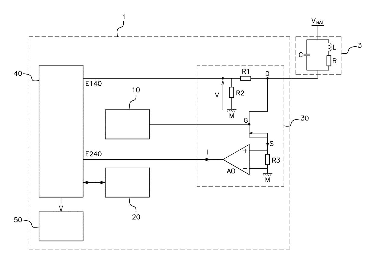
[0040]With reference to FIG. 1, the electronic control unit 1 according to the invention is intended to be fitted in a motor vehicle (not shown) to allow the voltage control, by pulse width modulated signals, of one or more electrical apparatuses 3 of said vehicle.

[0041]For the sake of clarity, FIG. 1 shows a single apparatus 3, but it goes without saying that the electronic control unit 1 could provide voltage control for more than one apparatus 3.

[0042]This electrical apparatus 3 can be electrically modeled in the form of an equivalent RLC circuit comprising a first branch, comprising a capacitor C connected in parallel with a second branch, comprising a resistor R and an induction coil L, both connected in series.

[0043]The apparatus 3 is electrically connected, on the one hand, to the battery VBAT of the vehicle, and, on the other hand, to the electronic control unit 1, at a point denoted by D.

[0044]With reference to FIG. 1, the electronic control unit 1 comprises a control modul...


PUM


Abstract

Disclosed is a method for controlling the voltage of an electrical apparatus of a motor vehicle. The method includes the steps of measuring (E2) the voltage at the terminals of the apparatus and measuring (E3) the strength of the output current of the apparatus, calculating (E4) the values of resistance, inductance and capacitance of the equivalent circuit on the basis of the measured current strength and the measured voltage, comparing (E7, E8, E9) the calculated values of resistance, inductance and capacitance with the values of resistance, inductance and capacitance, respectively, stored in a storage area of the electronic control unit, and initiating (E12) an action if the difference between at least one of the calculated values and the corresponding stored value is above a predetermined threshold.

Description

FIELD OF THE INVENTION[0001]The invention relates to the field of the voltage control of an apparatus, and more particularly to a device and a method for controlling the voltage of an apparatus fitted in a motor vehicle.BACKGROUND OF THE INVENTION[0002]The invention may be applied, notably, to the voltage control of an apparatus by pulse width modulated signals, referred to in English as “PWM” or “pulse width modulation” signals.[0003]In a motor vehicle, some apparatuses are controlled in a known way by a control unit, using pulse width modulated voltage control signals (PWM signals). The apparatus may be, for example, an ignition coil, a fuel injector, a fuel pump, an idle valve, or the like.[0004]Pulse width modulation is a commonly used technique for synthesizing continuous signals using circuits with on / off operation, or more generally circuits having discrete states. The general principle is that, by applying a sequence of discrete states during carefully selected time interval...

Claims


Application Information

Patent Timeline
Patent Type & Authority Patents(United States)
IPC IPC(8): B60R16/03G01R19/00G01R27/08G01R27/26
CPCB60R16/03G01R19/0046G01R27/2611G01R27/2605G01R27/08G05F1/56B60L3/12G05F1/10H03K7/08
Inventor PINEL, ARNAUDVITALI, STEPHANE
Owner VITESCO TECH GERMANY GMBH
Learn More