Battery voltage balance apparatus and battery charge apparatus
a battery voltage balance and charge device technology, applied in charge equalisation circuits, transportation and packaging, arrangements for several simultaneous batteries, etc., can solve the problems of high unnecessary power consumption as well as heat generation, and reduce the cost of digital battery balance controllers. , the effect of reducing the cost of the battery balance controller
- Summary
- Abstract
- Description
- Claims
- Application Information
AI Technical Summary
Benefits of technology
Problems solved by technology
Method used
Image

Examples
first embodiment
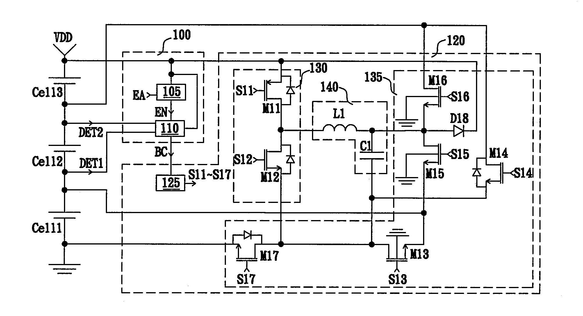
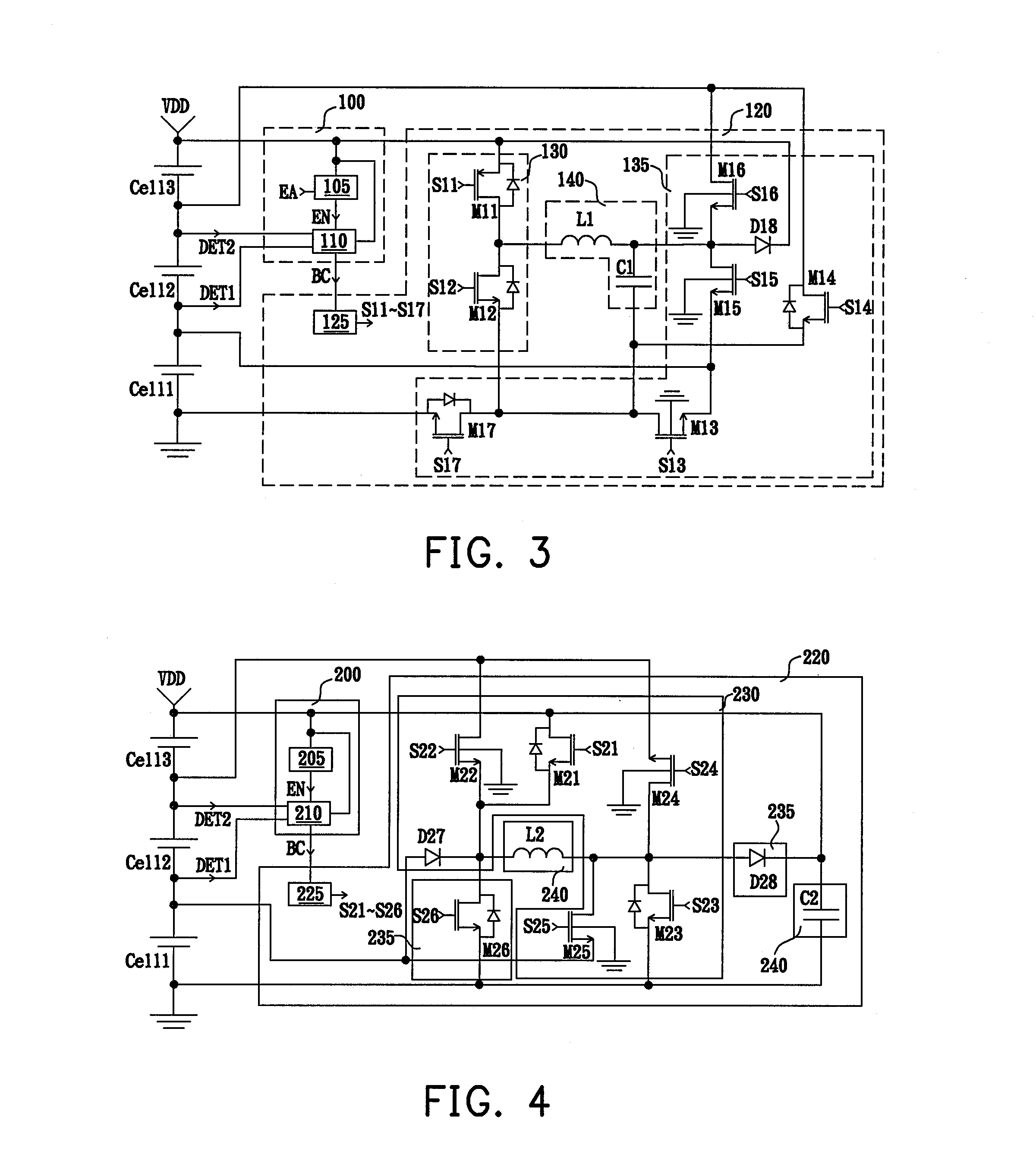
[0024]FIG. 3 is a schematic circuit diagram of a battery voltage balance apparatus according to the invention. Referring to FIG. 3, the battery charge apparatus is coupled to a battery module having a plurality of battery units Cell1, Cell2, and Cell3 connected in series, and includes a balance determining unit 100 and a converting unit 120. The balance determining unit 100 includes a start circuit 105 and a voltage balance determining circuit 110. The start circuit 105 determines whether the voltage VDD is higher than a predetermined start voltage. Herein, the voltage VDD is provided by the plurality of battery units Cell1, Cell2, and Cell3 connected in series. If the voltage VDD is higher than the predetermined start voltage, the start circuit 105 generates a voltage determining start signal EN to ensure that the battery voltage balance apparatus can operate with a high enough driving voltage, thereby avoiding an erroneous operation due to the insufficient driving voltage. Further...
second embodiment
[0033]FIG. 4 is a schematic circuit diagram of a battery voltage balance apparatus according to the invention. Referring to FIG. 4, in the present embodiment, the converting unit 220 is a boost converting circuit. The battery voltage balance apparatus is coupled to a plurality of battery units Cell1, Cell2, and Cell3 connected in series, and includes a balance determining unit 200 and a converting unit 220. The balance determining unit 200 includes a start circuit 205 and a voltage balance determining circuit 210. Herein, the start circuit 205 is used to determine whether the voltage VDD is higher than a predetermined start voltage to generate a voltage determining start signal EN to start the battery voltage balance apparatus. When receiving the voltage determining start signal EN, the voltage balance determining unit 210 starts to detect the battery voltages of each battery units according to the battery voltage detecting signals DET1 and DET 2 and the positive end and the negativ...
third embodiment
[0038]FIG. 5 is a schematic circuit diagram of a battery voltage balance apparatus according to the invention. Referring to FIG. 5, the battery voltage balance apparatus includes a balance determining unit 300 and a converting unit 320 and is coupled to a plurality of battery units Cell1 and Cell2 connected in series. In the present embodiment and the following embodiment, in order to explain briefly, the battery module having the battery units Cell1 and Cell2 are taken as an example.
[0039]The balance determining unit 300 includes a start circuit 305 and a voltage balance determining circuit 310. Herein, after receiving the start signal EA, the start circuit 305 starts to determine whether the voltage VDD is higher than a predetermined start voltage. If so, the start circuit 305 generates a voltage determining start signal EN to start the battery voltage balance apparatus. When receiving the voltage determining start signal EN, the voltage balance determining unit 310 starts to dete...
PUM
 Abstract
Description
Claims
Application Information
 - R&D
- Intellectual Property
- Life Sciences
- Materials
- Tech Scout
- Unparalleled Data Quality
- Higher Quality Content
- 60% Fewer Hallucinations
Browse by: Latest US Patents, China's latest patents, Technical Efficacy Thesaurus, Application Domain, Technology Topic, Popular Technical Reports.
© 2025 PatSnap. All rights reserved.Legal|Privacy policy|Modern Slavery Act Transparency Statement|Sitemap|About US| Contact US: help@patsnap.com