
Furnace lining

Inactive Publication Date: 2011-05-12
ELMELIN
View PDF11 Cites 12 Cited by
  • Summary
  • Abstract
  • Description
  • Claims
  • Application Information

AI Technical Summary

Benefits of technology

[0012]The metal foil within the flexible lining material is impervious to the penetration of metal vapour and so will prevent harmful metal vapours from condensing onto the induction coil.

Problems solved by technology

The use of an extremely thin layer of non-magnetic stainless steel foil within the lining material makes this vapour barrier substantially un-affected by the induced currents produced by the furnace.
As a result the flexible lining material of the invention will not become substantially heated by the induction field generated by the furnace and therefore will not significantly reduce its operating efficiency.

Method used


Image

  • Furnace lining
  • Furnace lining
  • Furnace lining

Examples


Embodiment Construction

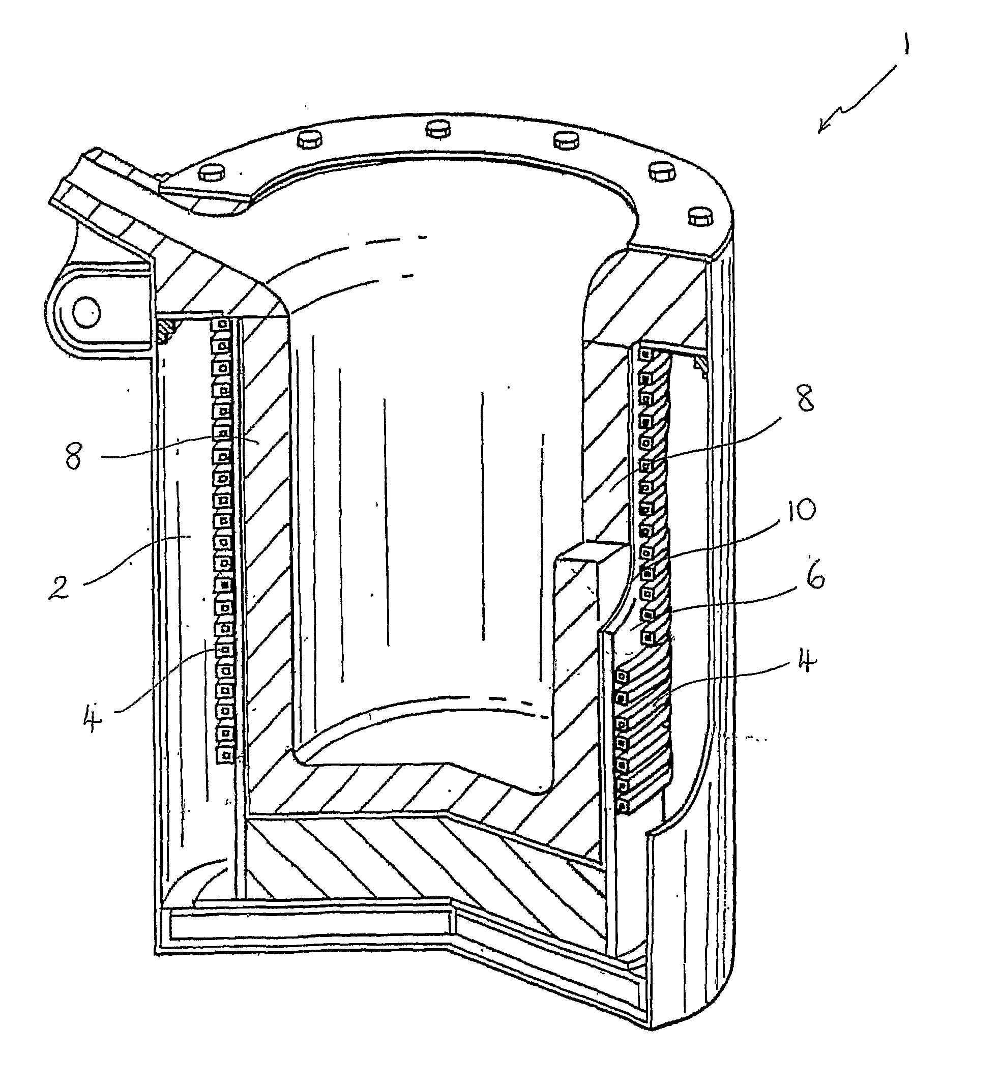
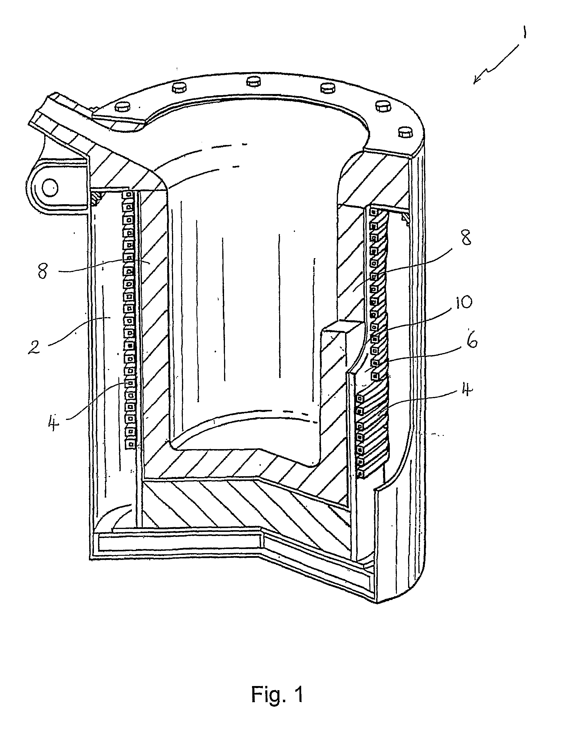
[0022]FIG. 1 shows a typical coreless induction furnace 1 comprising an outer jacket 2, with a water-cooled induction coil 4 within the jacket. The coil 4 is generally made of copper. On the inside of the coil 4, there is a thin layer of refractory plaster, usually 8-10 mm thick, called the coil grout 6 which forms a smooth surface on the inside of the furnace 1, as well as protecting the coil 4.

[0023]To form a crucible 8, a cylindrical former (not shown) typically of a diameter 200-250 mm smaller than the coil 4 is temporarily placed inside the furnace and refractory sand is rammed into the space between the coil grout 6 and the former. The refractory sand is then compacted in a conventional manner.

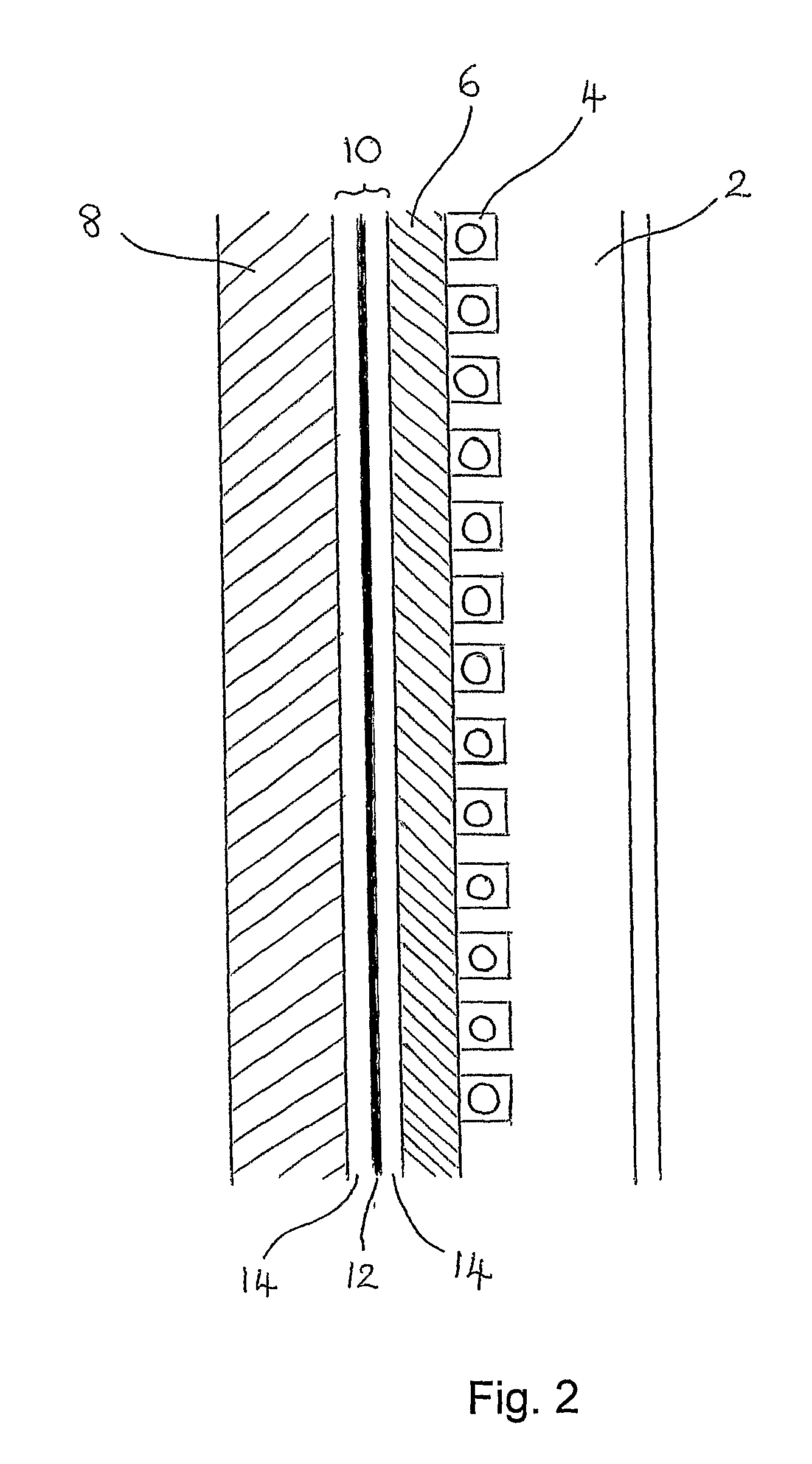
[0024]A lining material 10 is provided between the coil grout 6 and the crucible 8, the construction and function of which will be described below.

[0025]The lining material 10 is a laminated structure comprising a thin metallic foil layer 12 interposed between two support layers 14, as s...


PUM

PropertyMeasurementUnit
Thicknessaaaaaaaaaa
Thicknessaaaaaaaaaa
Thicknessaaaaaaaaaa

Abstract

This invention relates to a lining for induction furnaces, and more specifically a lining for coreless induction furnaces. A flexible lining material (10) for lining an induction furnace (1) has a laminated structure comprising metal foil (12) and at least one heat-resistant supporting layer (14). The incorporation of a very thin metallic foil layer (12) in the lining material (10) creates a vapour barrier preventing vapours such as zinc from reaching the induction coil (4) of the furnace. The lining material (10) is designed so that the metal foil (12) is not significantly affected by the induction fields during the operation of the furnace.

Description

BACKGROUND[0001]a. Field of the Invention[0002]This invention relates to a lining material and method of lining a coreless induction furnace.[0003]b. Related Art[0004]Electrically powered induction furnaces and coreless induction furnaces in particular are widely used in foundries to provide the molten metal used to make castings.[0005]Coreless induction furnaces typically comprise a refractory crucible inside a water-cooled induction coil. The inner face of the induction coil is usually covered by a thin layer of refractory plaster which is called the coil grout. To form the crucible, a former is placed temporarily inside the coil. Refractory sand is then rammed into the space between the coil grout and a cylindrical former and compacted to form the crucible.[0006]It is known to provide a layer between the coil grout and the crucible to provide a slip plane between these surfaces so that movement can take place between these surfaces during the heating and cooling of the furnace, a...

Claims


Application Information

Patent Timeline
IPC IPC(8): F27D1/00B32B15/04F27D1/16
CPCF27B14/08F27D1/0006Y10T428/251Y10T428/264Y10T428/265F27D1/1678F27B14/061F27D11/06H05B6/24
Inventor WEISS, STEPHEN STEWART
Owner ELMELIN
Features
  • Generate Ideas
  • Intellectual Property
  • Life Sciences
  • Materials
  • Tech Scout
  • Unparalleled Data Quality
  • Higher Quality Content
  • 60% Fewer Hallucinations
Learn More