
Communication apparatus, interface card, and failure handling method

Inactive Publication Date: 2011-05-12
FUJITSU LTD
View PDF11 Cites 7 Cited by
  • Summary
  • Abstract
  • Description
  • Claims
  • Application Information

AI Technical Summary

Benefits of technology

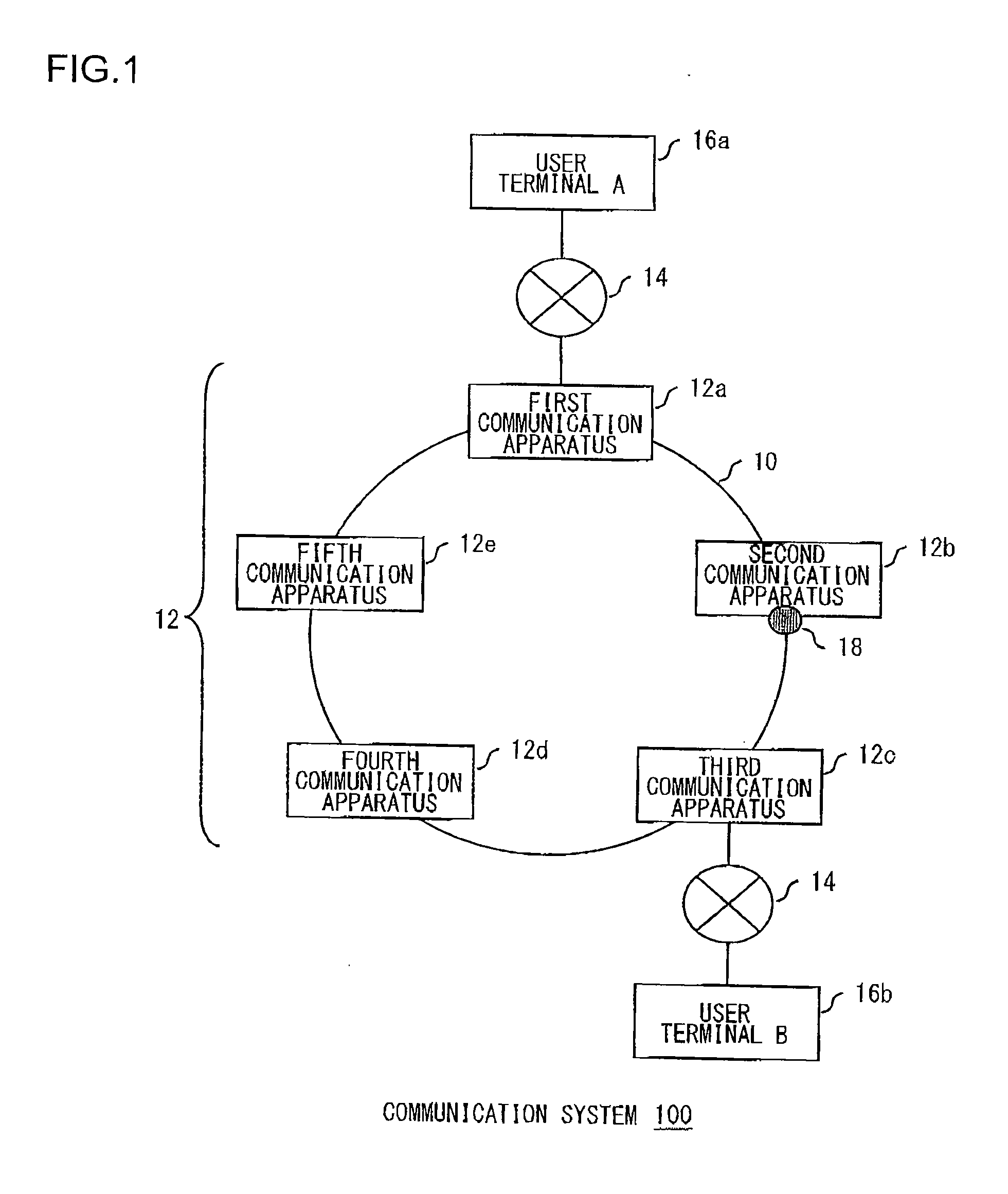
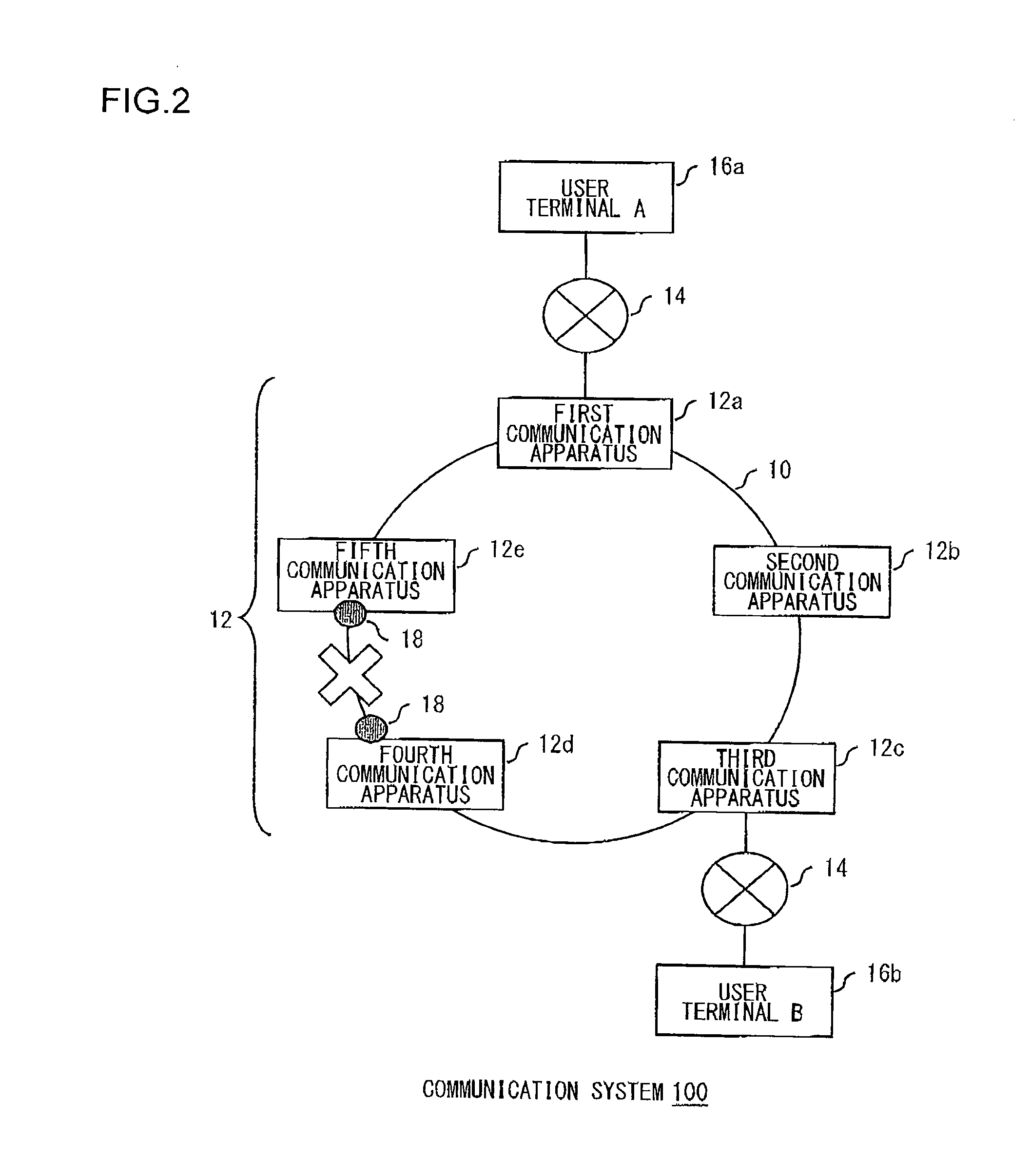
[0011]According to the present embodiment, in the case a failure is generated inside a communication apparatus, a new block point of the communication apparatus is set. As a result, the transmission path of a data frame is changed based on the ring protocol so as to bypass the new block point. This allows for the transmission of a data frame to be easily maintained even when a failure is generated inside the communication apparatus.
[0014]According to the present embodiment, a block point can be set to a relay unit in which a failure is generated. This ensures the relay of a data frame with the ring network 10 via a relay unit in which no failure is generated, allowing for the data frame to be relayed by a communication apparatus to be easily saved.
[0019]According to the present embodiment, the internal communication status is monitored in either the first relay unit or the second relay unit, and depending on the abnormality of the internal communication status, a block point is set to the relay unit corresponding to the internal communication status. In other words, the internal communication status does not need to be monitored in all the relay units, and a communication apparatus can thus be achieved that allows interfaces with different intervals for monitoring to coexist. In addition, gradual enhancement of functions in units of relay units can be achieved in the communication apparatus.
[0021]According to the present embodiment, with regard to either the first relay unit or the second relay unit, the relay of a data frame via the relay unit can be disconnected in an integrated fashion even when the relay unit has an external interface to multiple communication networks. In other words, the internal communication status does not need to be monitored in all the relay units, and a communication apparatus can thus be achieved that allows interfaces with different intervals for monitoring to coexist. In addition, gradual enhancement of functions in units of relay units can be achieved in the communication apparatus.
[0024]According to the present embodiment, an interface card can be realized to which a new block point is to be set in the ring network, depending on the communication status of another interface card. In other words, a preferred interface card is realized for improving the fault tolerance of the ring network.
[0025]Still another embodiment of the present invention relates to a failure handling method. The failure handling method performed by the communication apparatus constituting a ring network where a block point that disconnects the relay of a data frame is set to at least one of a plurality of communication apparatuses that are connected in a ring shape comprises: monitoring the communication status inside the apparatus from the interface in the first direction of the ring network to the interface in the second direction, which is different from the first direction; setting a new block point to either the interface in the first direction or the interface in the second direction when the communication status is abnormal; and notifying other communication apparatuses that constitute the ring network of information for notifying the switching of a block point in the ring network, which indicates that the new block point has been set. According to the present embodiment, the transmission of a data frame can be easily maintained even when a failure is generated inside the communication apparatus as described above.

Problems solved by technology

The transmission of the data frames is not sometimes able to be maintained when a failure is generated inside the communication apparatuses.

Method used


Image

  • Communication apparatus, interface card, and failure handling method
  • Communication apparatus, interface card, and failure handling method
  • Communication apparatus, interface card, and failure handling method

Examples


first embodiment

[0055]FIG. 5 is a block diagram illustrating a functional configuration, in the first embodiment, of the communication apparatus 12 shown in FIG. 1. The communication apparatus 12 is provided with a first IF card 20, a second IF card 22, a third IF card 24, a switching unit 26, and an operation control unit 28.

[0056]The blocks shown in the block diagram of the specification are implemented in the hardware by any CPU or memory of a computer, other elements, or mechanical devices, and in software by a computer program or the like. FIG. 2 depicts functional blocks implemented by the cooperation of hardware and software. Thus, a person skilled in the art should appreciate that there are many ways of accomplishing these functional blocks in various forms in accordance with the components of the combination of hardware and software. For example, the first IF card 20, the second IF card 22, the third IF card 24, and the switching unit 26 all shown in FIG. 5 may be achieved by hardware, and...

second embodiment

[0077]In the first embodiment, one interval for monitoring, from the first IF card 20 to the second IF card 22, is provided, and a block point is set to the first IF card 20 or to the second IF card 22 upon the generation of a failure inside the communication apparatus 12. Therefore, a block point may be set to the second IF card 22 even when the failure is generated inside the first IF card 20. In this case, a data frame cannot be relayed between the communication apparatus 12 and the ring network 10 even when the second IF card 22 is normal. In the present embodiment, the interval for monitoring, from the first IF card 20 to the second IF card 22, is segmentalized so as to set a block point to an appropriate interface card.

[0078]FIG. 8 is a block diagram illustrating a functional configuration, in the second embodiment, of the communication apparatus 12 shown in FIG. 1. In the figure, like numerals represent like functional blocks in FIG. 5, and the overlapping description thereof...

third embodiment

[0092]There are some interface cards that are provided with multiple ports where the ports are connected to a different communication network (hereinafter, referred to as a “first ring network 10a” and a “second ring network 10b”), respectively. Such an interface card is provided with multiple external IF processors 50 shown in FIG. 8. The external IF processors 50 are hereinafter referred to as an “external IF processor A 50a” and an “external IF processor B 50b,” The internal IF processor 60 acquires data frames each output from the external IF processor A 50a and the external IF processor B 50b and passes the data frames to the switching unit 26 in an integrated fashion.

[0093]In such an interface card, when a block point is to be set in accordance with the communication status between the external IF processor A 50 a and the internal IF processor 60 and with the communication status between the external IF processor B 50b and the internal IF processor 60, it is desirable that at ...


PUM


Abstract

A communication apparatus of the embodiment is provided with a first IF card that performs a relay process of a data frame in a first direction of a ring network, a second IF card that performs a relay process of a data frame in a second direction of the ring network, a communication-status determination unit that monitors the communication status from the first IF card to the second IF card, a block control unit that sets a new block point to either the first IF card or the second IF card when the communication status is abnormal, and a ring protocol processor that notifies other communication apparatuses that constitute the ring network of information for notifying the switching of a block point in the ring network, which indicates that the new block point has been set.

Description

BACKGROUND OF THE INVENTION[0001]1. Field of the Invention[0002]The present invention relates to data communication techniques and particularly to communication apparatuses that constitute a ring network, to interface cards to be installed in the communication apparatuses, and to a failure handling method performed by the communication apparatuses.[0003]2. Description of the Related Art[0004]As a highly-reliable communication network, a communication network in which multiple communication apparatuses that relay a data frame are connected in a ring shape, that is, a so-called ring network is often built. Data frame looping needs to be prevented in a ring network. Thus, by using a protocol for ring control (hereinafter, referred to as a“ring protocol”), at least one port of a communication apparatus is often set as a port that blocks the relay of a data frame (hereinafter, referred to as a “block point”).[0005]Upon the generation of a failure in the communication line between communi...

Claims


Application Information

Patent Timeline
IPC IPC(8): G06F15/173G06F15/16
CPCH04J3/085H04J2203/006H04L43/0811H04L41/0663H04L12/437
Inventor MARUYAMA, RYO
Owner FUJITSU LTD
Learn More