Method of installing an elevator

a technology of elevators and guide rails, applied in elevators, mine lifts, building material handling, etc., can solve the problems of inability to support the guide rails, the hoisting capacity needed to perform the last jump-lift is extremely large, and the worksite crane is not always available when needed, etc., to achieve the effect of easy handling/use/access and the same lifting ratio

Inactive Publication Date: 2011-05-19
KONE CORP
View PDF18 Cites 34 Cited by
  • Summary
  • Abstract
  • Description
  • Claims
  • Application Information

AI Technical Summary

Benefits of technology

[0009]The aim of the invention is to eliminate, among others, the aforementioned drawbacks of prior-art solutions. More particularly the aim of the invention is to produce an improved construction-time elevator arrangement and method, by utilizing which the construction-time operating range of an elevator can be extended upwards in the building. The aim of the invention is further to produce one or more of the following advantages, among others:
[0010]A solution is achieved with which very large masses can be moved with a simple arrangement.

Problems solved by technology

One problem with this type of arrangement is that the worksite crane is not always available when needed.
Owing to the very great travel heights of modern elevators, the machine size and rope masses, among other things, are so great that the hoisting capacity needed to perform the last jump-lifts is extremely large.
The aforementioned solution supported on the guide rails cannot, for this reason, be used in all cases, because a weight that is heavier than the machine room platforms cannot be allocated to rest on the guide rails.
In solutions of this type, the hoisting apparatus tends to be large in size, complex, expensive to manufacture and laborious to install.
Methods used in the above type elevator installations have multiple stages and complex requirements.
The installation environment is complex, as important safety requirements, component strength and layout requirements need to be taken into account.
One general problem of the existing solutions has been that the solutions tend to get complex whereby it is challenging to design the system to be sufficiently efficient.

Method used


Image

  • Method of installing an elevator
  • Method of installing an elevator
  • Method of installing an elevator

Examples


Embodiment Construction

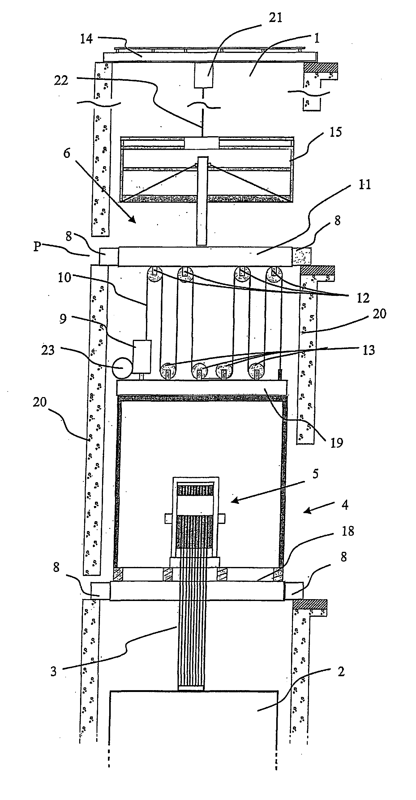
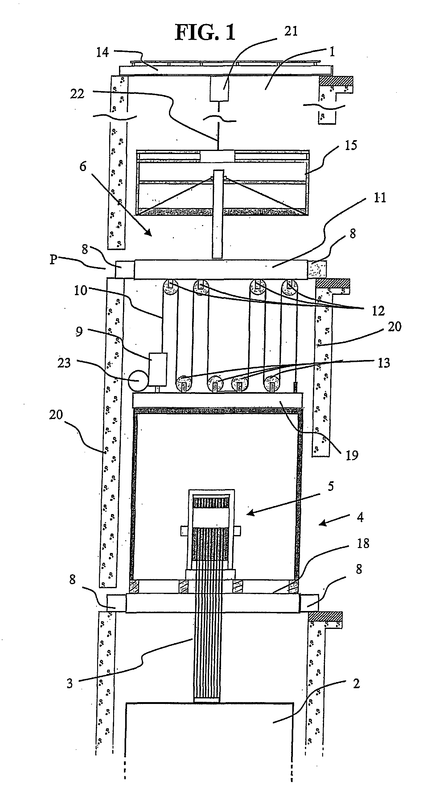
[0066]FIG. 1 presents an arrangement according to the invention in a construction-time elevator. The arrangement comprises a supporting platform 4 fitted into the elevator hoistway 1, which supporting platform supports the elevator car 2 below it via hoisting roping 3, which elevator car 2 is in use to serve passengers in the lower floors of the building. When the construction of the elevator hoistway has progressed to a sufficient stage of completion, a jump-lift can be performed utilizing the arrangement for changing the range of movement of the elevator car 2 in steps so that it reaches to higher in the elevator hoistway 1. This is arranged to be performed by lifting the supporting platform upwards in the elevator hoistway 1. For this purpose the arrangement according to the invention comprises a movable support structure 6 supported on the wall structures of the elevator hoistway above the supporting platform 4, as well as hoisting means (9,9′,10,10′) arranged to act between the...


PUM

PropertyMeasurementUnit
timeaaaaaaaaaa
forceaaaaaaaaaa
weightaaaaaaaaaa

Abstract

In a method in the use of a construction-time elevator, at least two lifts are performed. In each of the lifts, the supporting platform is lifted higher in the elevator hoistway with the hoisting device supported by the support structure so as to extend the operating range of the elevator car to reach higher in the elevator hoistway. A second support structure and a second hoisting device, which are above the support structure, are used between the lifts of the supporting platform, for moving the working platform in the elevator hoistway under construction between the second support structure and the support structure, and for lifting the support structure upwards in the elevator hoistway.

Description

CROSS-REFERENCE TO RELATED APPLICATIONS[0001]This application is a Continuation-In-Part of copending PCT International Application No. PCT / FI2010 / 000018 filed on Mar. 5, 2010, which designated the United States, and on which priority is claimed under 35 U.S.C. §120. PCT International Application No. PCT / FI2010 / 000018 claims priority to Application No. 20090085, filed in Finland on Mar. 6, 2009. The entire contents of each of the above-identified applications is hereby incorporated by reference.BACKGROUND OF THE INVENTION[0002]1. Field of the Invention[0003]The present application is directed to a method in installing an elevator, which elevator is used during construction time.[0004]2. Description of Background Art[0005]In connection with so-called jump-lifts, the bottom part of an elevator hoistway is taken into use before the building has been completed. In this case the top part of the elevator hoistway can be constructed at the same time as an elevator moving in the bottom part ...

Claims


Application Information

Patent Timeline
Patent Type & Authority Applications(United States)
IPC IPC(8): B66B11/04B66B7/02E04G21/00
CPCB66B19/00Y10T29/49828Y10T29/49947Y10T29/49904
Inventor PEACOCK, MARKPERALA, JUSSIESKELINEN, MATTIYAN, ZHIZHONG
Owner KONE CORP
Why Eureka
Try Eureka