
Fluid well pumping system and method to produce same

a technology of fluid well and pumping system, which is applied in the direction of fluid removal, earth-moving drilling, and wellbore/well accessories, etc., can solve the problems of not anticipating material and method security, pumping system or device, etc., and achieves the effects of less corrosion, less resistance, and simple structur

Inactive Publication Date: 2011-05-19
AIRELEVATOR SERVICES INT INC
View PDF11 Cites 0 Cited by
  • Summary
  • Abstract
  • Description
  • Claims
  • Application Information

AI Technical Summary

Benefits of technology

There are several objects and advantages of the Improved Fluid well pumping system 31. There are currently no known fluid pumping devices of such materials and configuration that are effective at providing the objects of this invention. It is an object of this invention to provide an improved fluid pumping system. It is a further object of this invention to provide a simple, efficient, low-cost, low-maintenance pumping system. It is an object to use new materials that are lighter, less resistive to pumped fluids and less corrosive than those known and used in any similar pump. Such materials and methods to secure are not anticipated by prior art fluid pumping systems or devices. Further objects, features and advantages of the present inventions shall become apparent from the detailed drawings and descriptions provided herein.
The invention presented is the Improved Fluid well pumping system 31. This device relates to a growing need for better means to pump fluids and other materials such as oil, water, sludge, gaseous fluids, or leachates from shallow to medium dept wells (0 to 4000 feet depths). This need is derived from a growing number of abandoned or idled oil and gas wells as well as abandoned or closed landfills and other lands that need a solution to pumping various materials.
The following TABLE A summarizes various advantages and objects of the Improved Fluid well pumping system 31. This list is exemplary and not limiting to the many advantages offered by this new device.
TABLE AVarious Benefits, Advantages and ObjectsThis device:ITEMBENEFIT1.Provides Maintenance free pumping2.Increases depth capability3.Increases flow capacities4.Reduces environmental risks5.Provides efficient continuous operation6.Improves overall system efficiency7.Simplifies and improves installation

Problems solved by technology

Such materials and methods to secure are not anticipated by prior art fluid pumping systems or devices.

Method used


Image

  • Fluid well pumping system and method to produce same
  • Fluid well pumping system and method to produce same
  • Fluid well pumping system and method to produce same

Examples


Embodiment Construction

The present invention presented is the Improved Fluid well pumping system 31. This device relates to pump systems that provide improved, low cost, efficient and low maintenance pumping systems for obtaining fluid from a source.

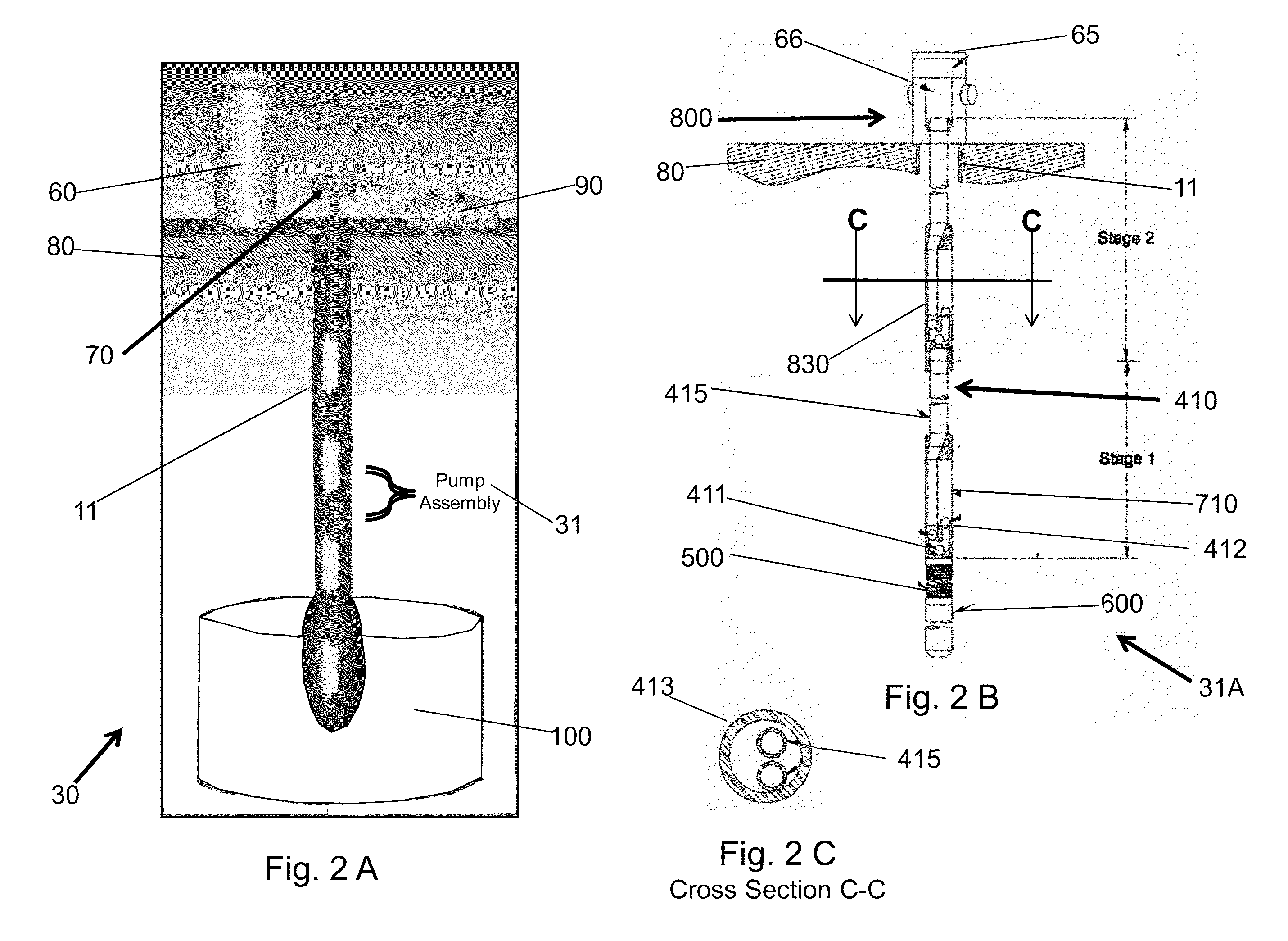
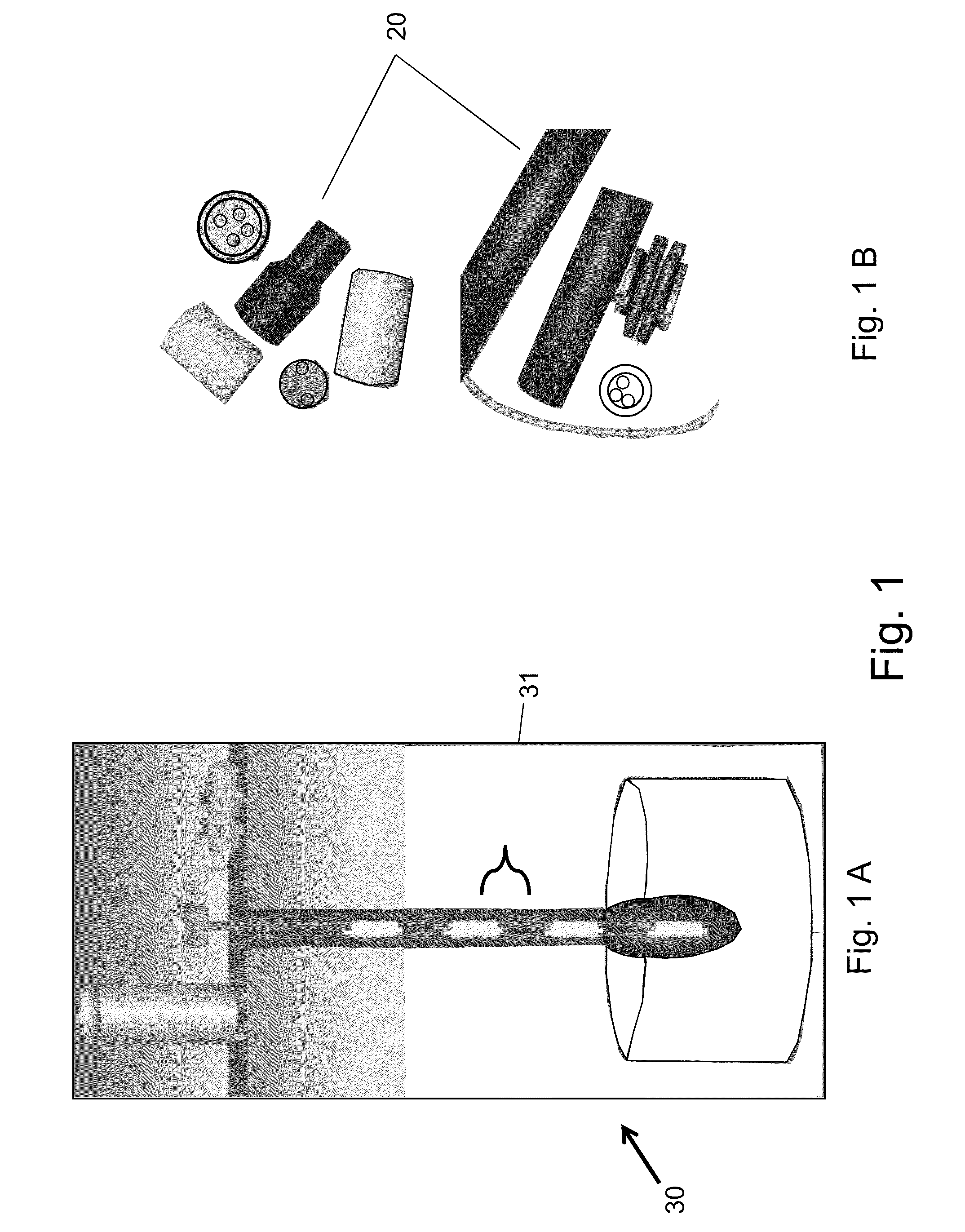
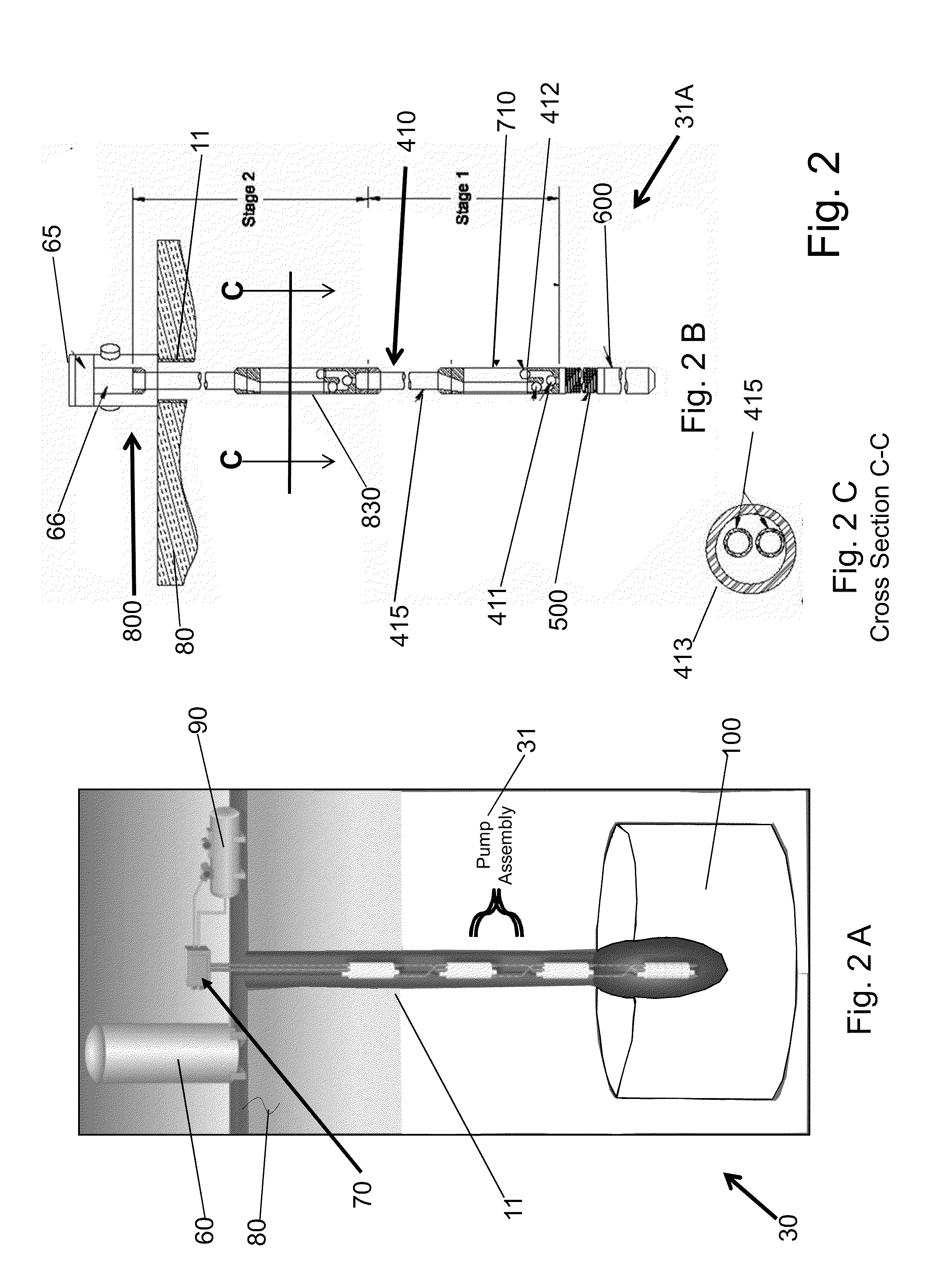
There is shown in FIGS. 1-17 a complete detail and operative embodiment of the Improved Fluid well pumping system 31. In the drawings and illustrations, one notes well that the FIGS. 1 through 12 show detail of the special configuration. FIGS. 13 through 17 describe its use and operation.

The advantages for the Improved Fluid well pumping system 31 are listed above in the introduction. Succinctly the benefits for the device are:Provides Maintenance free pumpingIncreases depth capabilityIncreases flow capacitiesReduces environmental risksProvides efficient continuous operationImproves overall system efficiencySimplifies and improves installation

The preferred embodiment of the device 31 is comprised of a pump assembly (located in the wellbore) and a control syste...


PUM


Abstract

An Improved Fluid well pumping system and method to produce the system. According to the system, it relates to ones that provide improved, low cost, efficient and low maintenance pumping systems for obtaining fluid from a source. It is envisioned that the systems will be used for removing oil, water, sludge, gaseous fluids, or leachates from shallow to medium depth wells (0 to 4000 feet depths). However, the invention has application for raising any fluids as needed above ground.

Description

FIELD OF INVENTIONThis invention for the Improved Fluid well pumping system is Fluid pumping systems and method to produce the system. According to the present invention, it relates to ones that provide improved, low cost, efficient and low maintenance pumping systems for obtaining fluid from a source. It is envisioned that the systems will be used for removing oil, water, sludge, gaseous fluids, or leachates from shallow to medium dept wells (0 to 4000 feet depths). However, the invention has application for raising any fluids as needed above ground.FEDERALLY SPONSORED RESEARCHNone.SEQUENCE LISTING OR PROGRAMNone.BACKGROUNDField of Invention and Prior ArtA. Introduction of the Problems AddressedPrior devices and methods included metallic and other complex fluid pumping systems. One skilled in the art and familiar with such means well appreciates the simplicity and cost effectiveness of this new device presented here. In the other prior art disclosures shown, complex and expensive a...

Claims


Application Information

Patent Timeline
Patent Type & Authority Applications(United States)
IPC IPC(8): E21B43/12
CPCE21B43/121E21B43/123
Inventor ROBERTS, DANIEL C.STOUGHTON, G RONALDWETZEL, JAMES R.
Owner AIRELEVATOR SERVICES INT INC
Learn More