Method and magnetic resonance system for imaging particles

a magnetic resonance system and particle technology, applied in the field of particle imaging methods, can solve the problems of long measurement time, hypointense image regions cannot be unambiguously associated, and signal loss, and achieve the effect of improving particle imaging

Inactive Publication Date: 2011-05-19
SIEMENS AG
View PDF16 Cites 10 Cited by
  • Summary
  • Abstract
  • Description
  • Claims
  • Application Information

AI Technical Summary

Benefits of technology

[0009]An object of the present invention is to avoid at least some of the aforementioned disadvantages and to improve the imaging of particles that are located in an examination subject.

Problems solved by technology

Particularly in T2*-weighted gradient echo (GRE) sequences, the interference of the homogeneous basic magnetic field leads to a signal loss.
One problem in this type of imaging of particles is that the hypointense image regions cannot be unambiguously associated with the particles since—as described above—there are multiple causes for a poor signal and corresponding dark image regions.
Such a procedure has the disadvantage of requiring long measurement times. Furthermore, due to the doubling of the measurement time the method is strongly susceptible to movements of the examined subject or patient, such that the acquired images contain movement artifacts.
Particularly in the subtraction of images, movements of the patient lead to image errors and thus to a loss of resolution and contrast in the imaging of the particles.

Method used


Image

  • Method and magnetic resonance system for imaging particles
  • Method and magnetic resonance system for imaging particles
  • Method and magnetic resonance system for imaging particles

Examples


Embodiment Construction

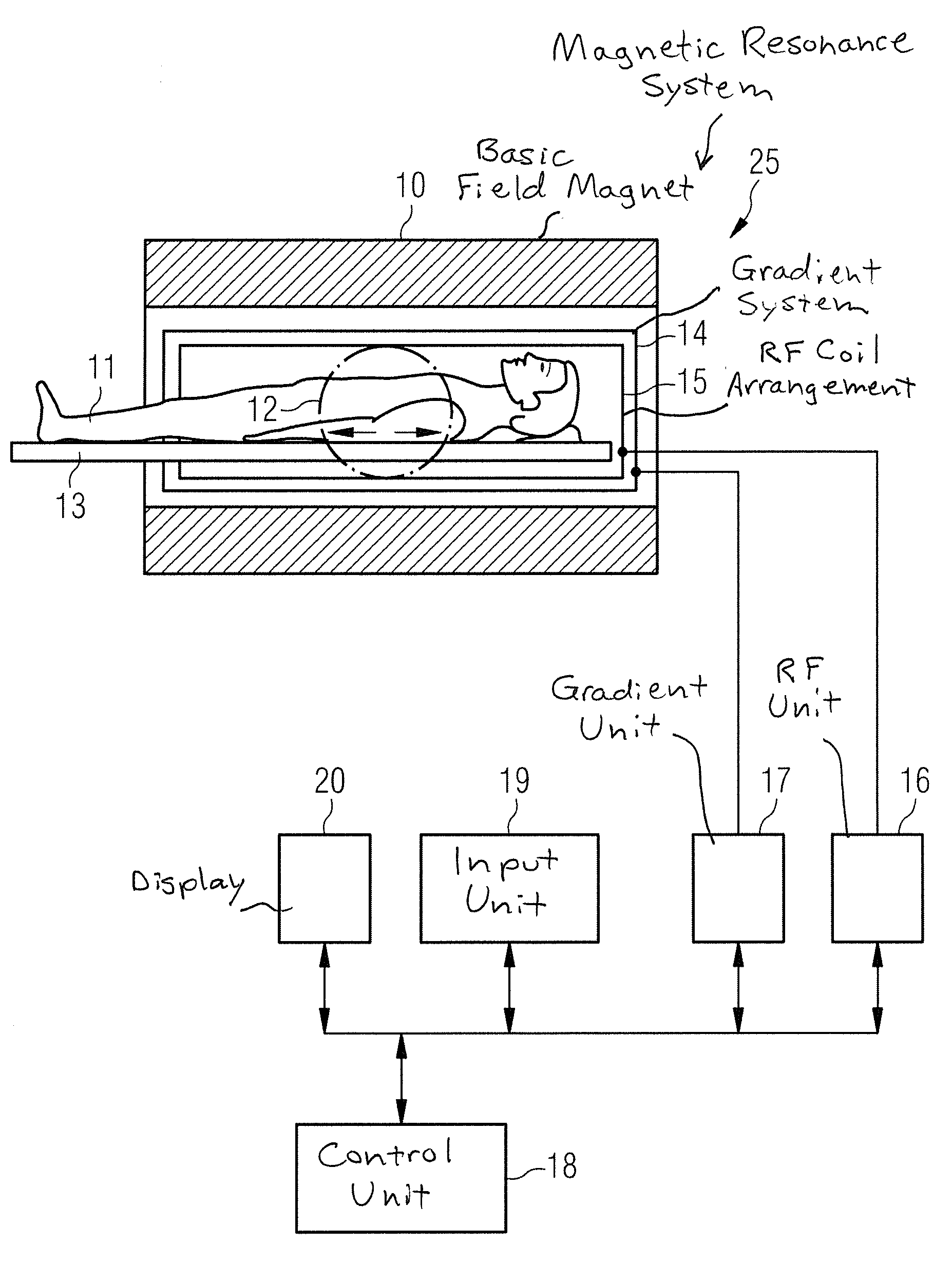
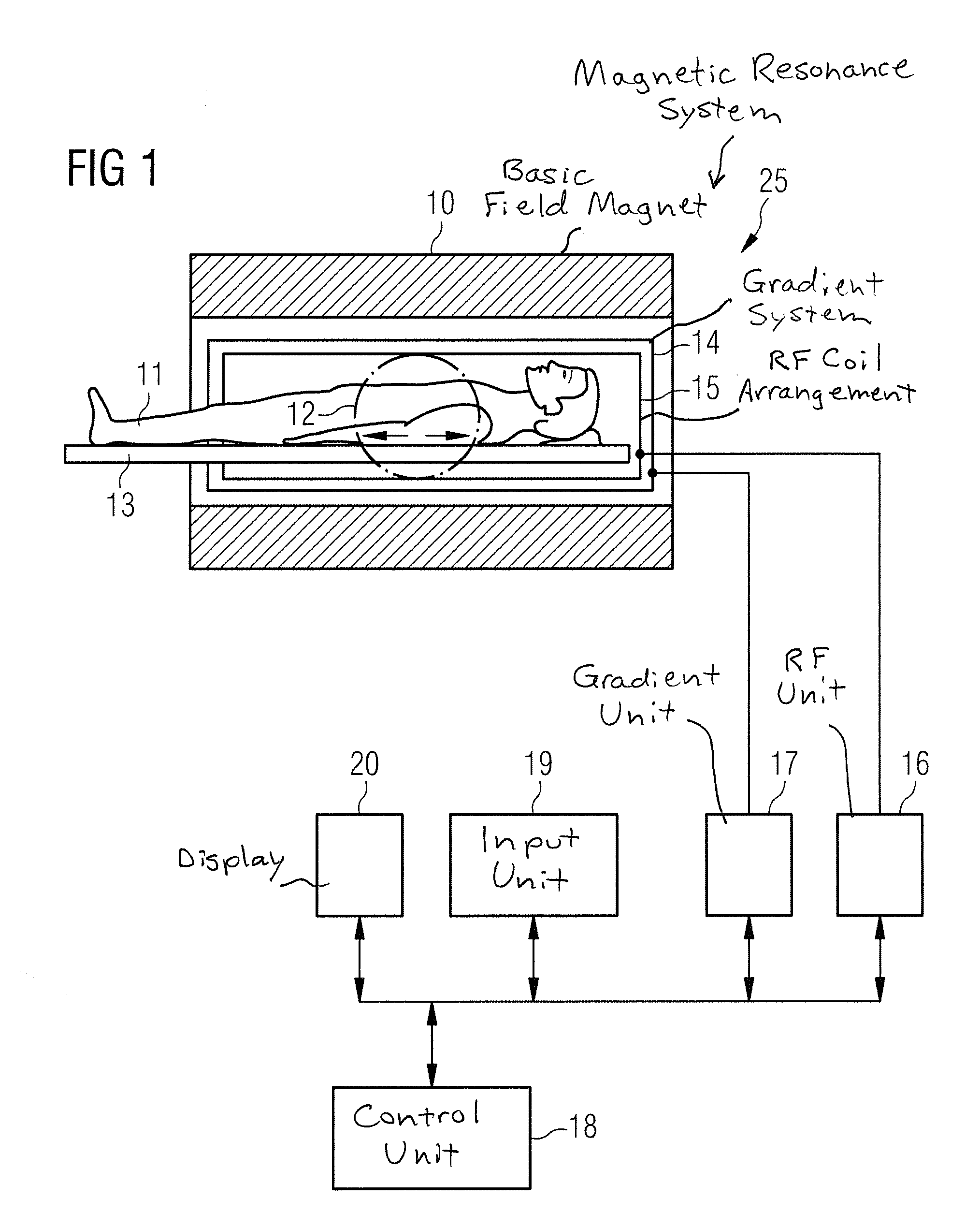
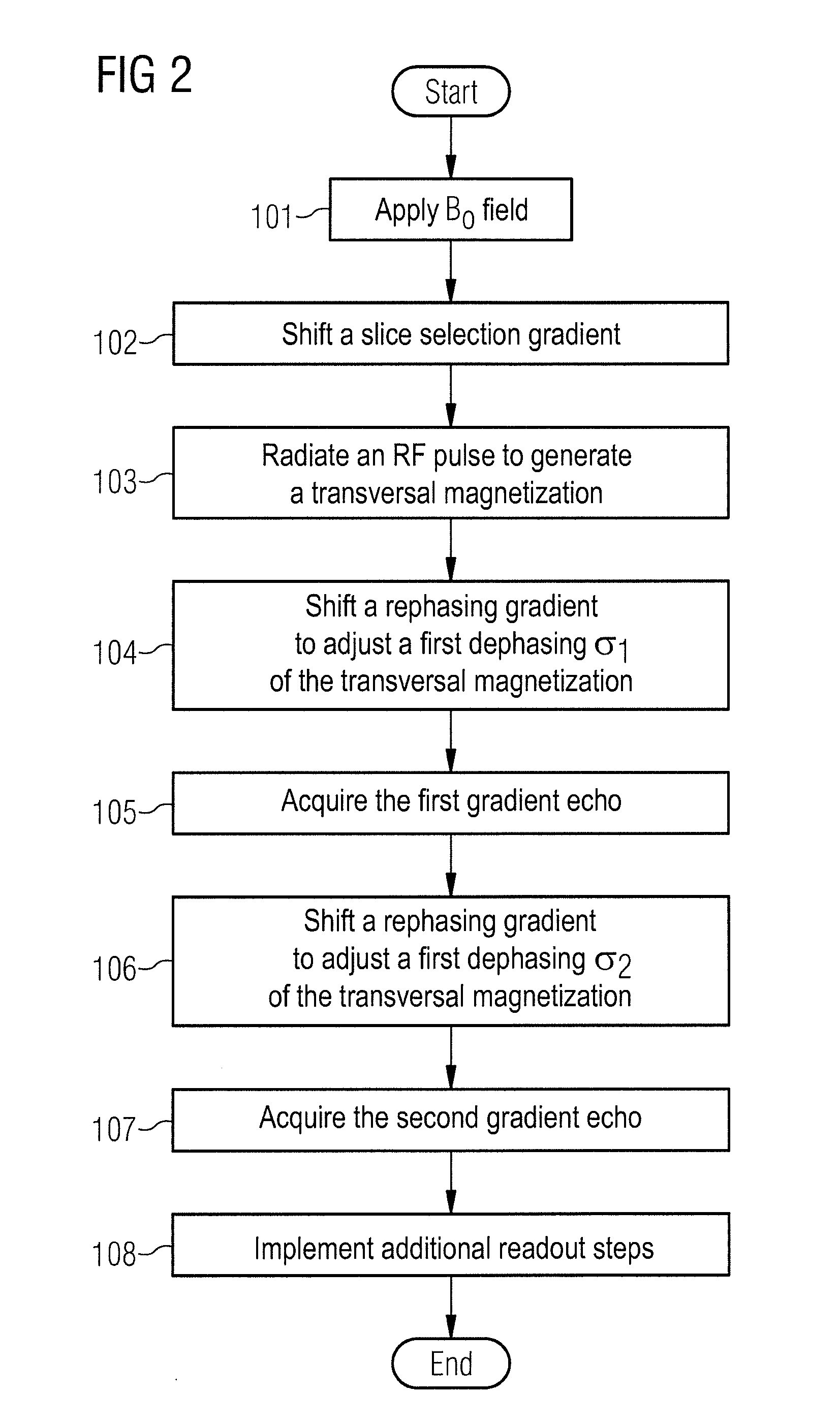
[0033]The imaging of magnetically active particles that generate an interference field (for example a dipole field) in an applied basic magnetic field is explained in detail using the embodiments of the present invention that are described in the following. In the gradient echo-based method, the dipole field generated by the particle is compensated via targeted dephasing in the readout, phase or slice coding direction in order to thus obtain an increased signal of protons that are located in the disrupted basic magnetic field. At the same time a weakened MR signal of the undistorted protons is acquired via the dephasing, such that the particle to be imaged can be shown with high contrast. The dephasing can be adjusted by uncompensated dephasing and rephasing gradients or via additional dephasing gradients. The strength of this adjustable dephasing can be specified in the unit “cycles per voxel (CpV)”, for example. A dephasing of the strength 1 CpV indicates that the phase difference...


PUM


Abstract

A method and magnetic resonance system for imaging a particle that is located in an examination subject with an imaging magnetic resonance measurement execute a gradient echo sequence in which at least two gradient echoes are acquired following a single excitation pulse, wherein the particle in an applied basic magnetic field causes a magnetic interference field. An RF pulse is radiated to generate a transverse magnetization from a magnetization appearing in the basic magnetic field. A first dephasing gradient is shifted to adjust a first dephasing of the transverse magnetization, and the first gradient echo is acquired. A second dephasing gradient is shifted to adjust a second dephasing of the transverse magnetization that is different than the first dephasing, and the second gradient echo is acquired. The two dephasing gradients are shifted such that a dephasing of the transverse magnetization caused by the interference field of the particle is at least partially compensated in a region around the particle or within the particle given the acquisition of at least one of the echoes.

Description

BACKGROUND OF THE INVENTION[0001]1. Field of the Invention[0002]The present invention concerns a method to image a particle that is located in an examination subject, as well as a magnetic resonance system for this purpose. The invention in particular concerns the imaging of a particle that causes a magnetic interference field in an applied basic magnetic field in a magnetic resonance measurement (scan).[0003]2. Description of the Prior Art[0004]Magnetic resonance tomography (MRT) is a modality in widespread use to graphically depict structures inside the body of a patient. To generate a magnetic resonance (MR) signal, in general protons of hydrogen molecules that are found in a prepared, magnetic state are excited. The decay of this excitation induces the MR signal in an acquisition coil. The MR signal is thus dependent on, among other things, the density of the protons of the hydrogen molecules. A very low magnetic resonance signal—which leads to a depiction of the corresponding r...

Claims


Application Information

Patent Timeline
Patent Type & Authority Applications(United States)
IPC IPC(8): G01R33/48
CPCA61B5/0515A61B5/055G01R33/56509G01R33/5601G01R33/56316A61B5/7207
Inventor GRODZKI, DAVID
Owner SIEMENS AG
Why Eureka
Try Eureka