

Method of cutting thin-walled material
a thin-walled material and cutting technology, applied in the direction of turning machine accessories, manufacturing tools, metal working devices, etc., can solve the problems of easy vibration or deformation of sintering particles
- Summary
- Abstract
- Description
- Claims
- Application Information
AI Technical Summary
Benefits of technology
Problems solved by technology
Method used
Image

Examples
first embodiment
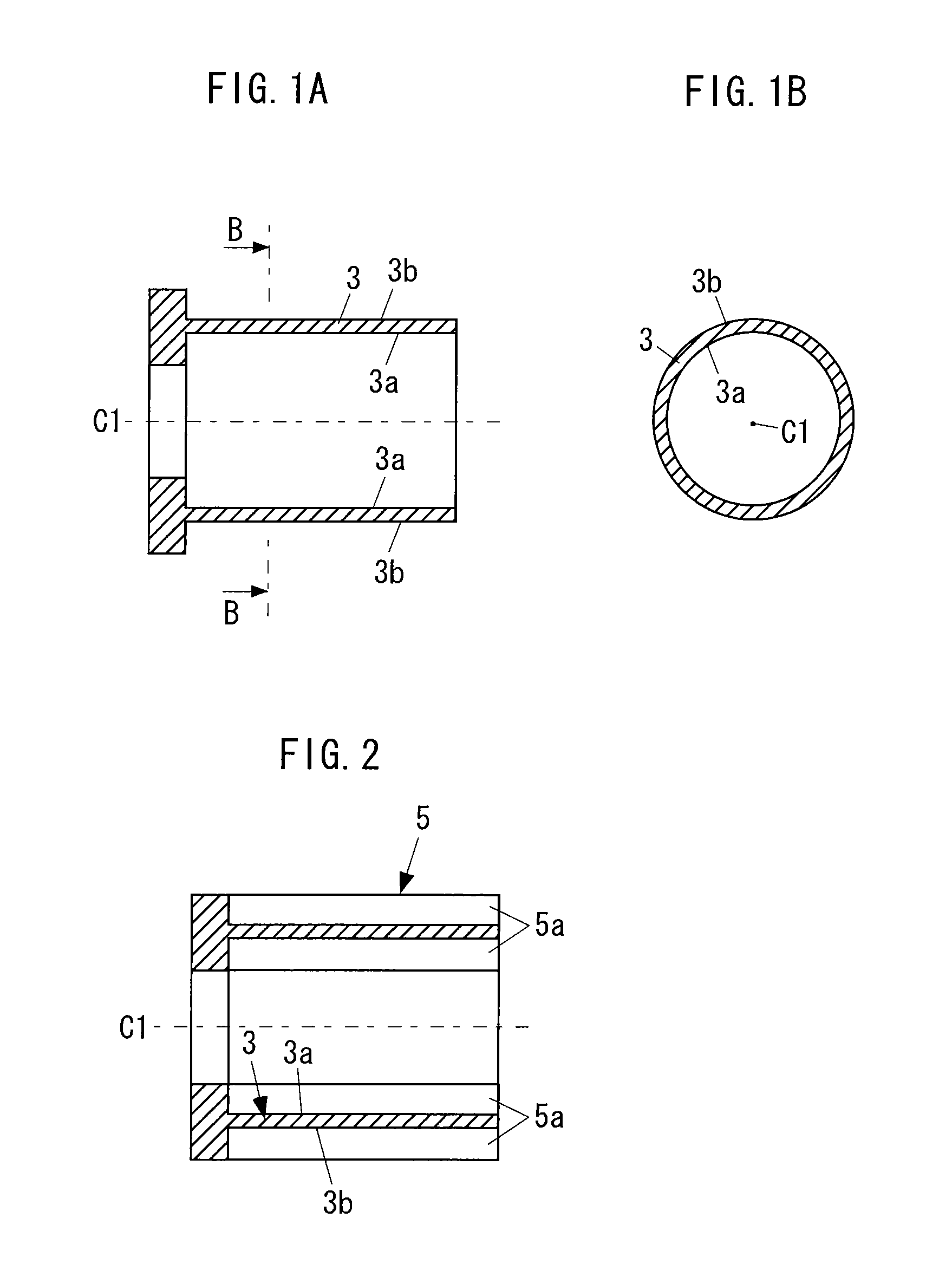
FIG. 1A is a transverse cross-sectional view of a thin-walled material 3 (that is, workpiece) which is fabricated by a cutting method according to a first embodiment of the present invention and FIG. 1B is a cross-sectional view taken along line B-B of FIG. 1A.
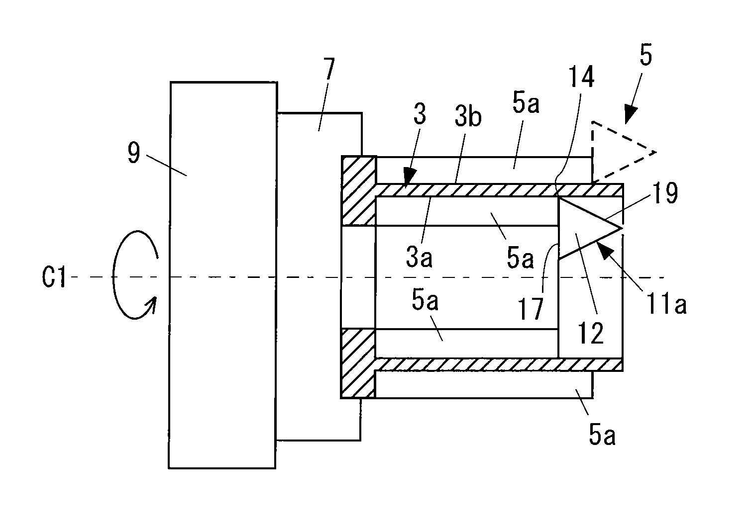
In this example, the thin-walled material 3 is a material which is provided at a rotating machine such as a jet engine, a gas turbine, or a supercharger and rotationally driven around a central axis C1 of the rotating machine. For example, the thin-walled material 3 may be the rotating shaft itself of the rotating machine or may also be a material which is mounted on and fixed to the rotating shaft.
As shown in FIGS. 1A and 1B, the thin-walled material 3 has an inner round surface 3a and an outer round surface 3b over a predetermined range in the direction parallel to the central axis C1 thereof. The expression “thin-walled” in the thin-walled material 3 means that the thickness between the inner round surface 3a and the outer ...
example 1
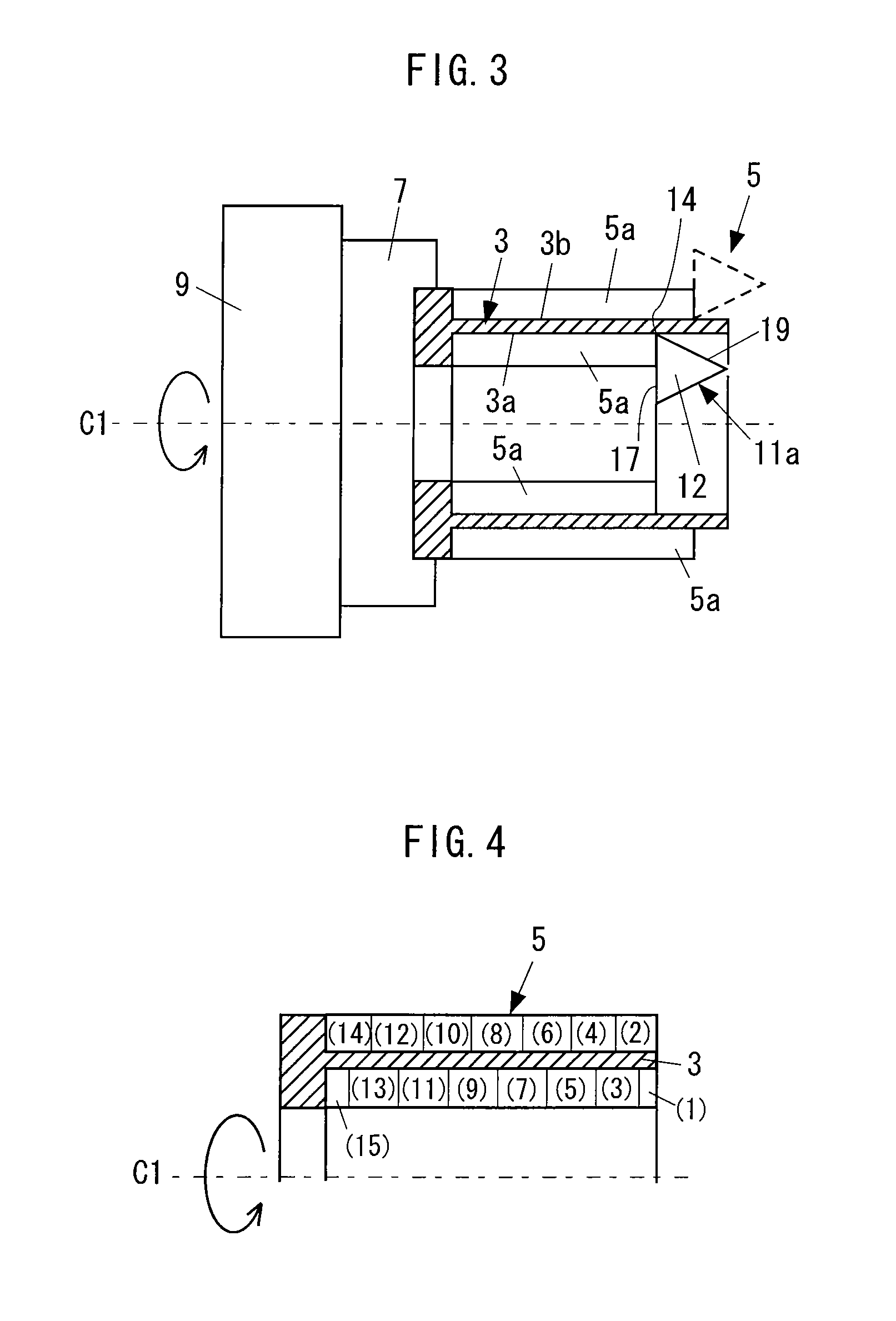
FIG. 9 illustrates another example of the cutting method according to the first embodiment described above.
In this drawing, the thin-walled material 3 has a labyrinth seal portion 13. Also, the material 5 is a forging subjected to rough cutting. Also, in this example, a support portion 15 of the material 5 is fixed to a rotating table (not shown) through an appropriate mounting tool (not shown) and cutting of the thin-walled material 3 is then performed.
In this example, the cutting method according to the first embodiment is applicable to an inner round surface 3a portion and an outer round surface 3b portion, which are shown in the drawing, and the steps S3 and S4 described above are performed alternately and repeatedly with respect to the inner round surface 3a portion and the outer round surface 3b portion in order of the numbers in parentheses in the drawing. That is, the inner round surface 3a and the outer round surface 3b are alternately formed little by little in order of ea...
example 2
FIG. 10 illustrates another example of the cutting method according to the first embodiment described above.
In this drawing, the thin-walled material 3 is a material constituting a casing of a combustor and is a stationary material which does not rotate at the time of use. Also, the material 5 has been subjected to rough cutting. Also, in this example, the thin-walled material 3 is fixed to the rotating table 9 through the mounting tool 7 and cutting of the thin-walled material 3 is then performed.
In this example, the steps S3 and S4 described above are performed alternately and repeatedly with respect to the inner round surface 3a portion and the outer round surface 3b portion, which are shown in the drawing, in order of the numbers in parentheses in the drawing. That is, the inner round surface 3a and the outer round surface3b are alternately formed little by little in order of each portion denoted by the numbers (1), (2), (3), . . . , (10), and (11).
In addition, cutting of a port...
PUM
| Property | Measurement | Unit |
|---|---|---|
| Angle | aaaaa | aaaaa |
| Angle | aaaaa | aaaaa |
| Thickness | aaaaa | aaaaa |
Abstract
Description
Claims
Application Information