Compound bow

a bow and string technology, applied in the field of compound bows, can solve the problems of not being able to easily control the bow cannot be disjointed and repaired on site with no equipment, etc., and achieve the effect of easy adjustment of the tension of the bow string

Inactive Publication Date: 2011-05-26
EEE CHANG HO
View PDF3 Cites 23 Cited by
  • Summary
  • Abstract
  • Description
  • Claims
  • Application Information

AI Technical Summary

Benefits of technology

[0010]To solve the above problems of the conventional art, it is an object of the present invention to provide a compound bow that enables a user to easily adjust tension of a bow string of the compound bow, and to freely disjoint and repair the compound bow with no special bow press equipment.
[0048]A compound bow according to the present invention has an advantage that enables a user to easily adjust tension of a bow string of the compound bow, and to freely disjoint and repair the compound bow with no special press equipment, when he or she intends to control tension of the bow string, or to repair or dismantle the bow at a time when the bow is not in use.

Problems solved by technology

By the way, the conventional compound bow has problems that tension of the bow string is not easily controlled during using the compound bow, and that equipment called a bow press having a specially large volume is needed in the case that there is a need to disjoint and repair the bow, to accordingly cause the bow not to be disjointed and repaired on site with no equipment.

Method used


Image

  • Compound bow
  • Compound bow
  • Compound bow

Examples


first embodiment

[0068]First, a compound bow according to this invention will be described below.

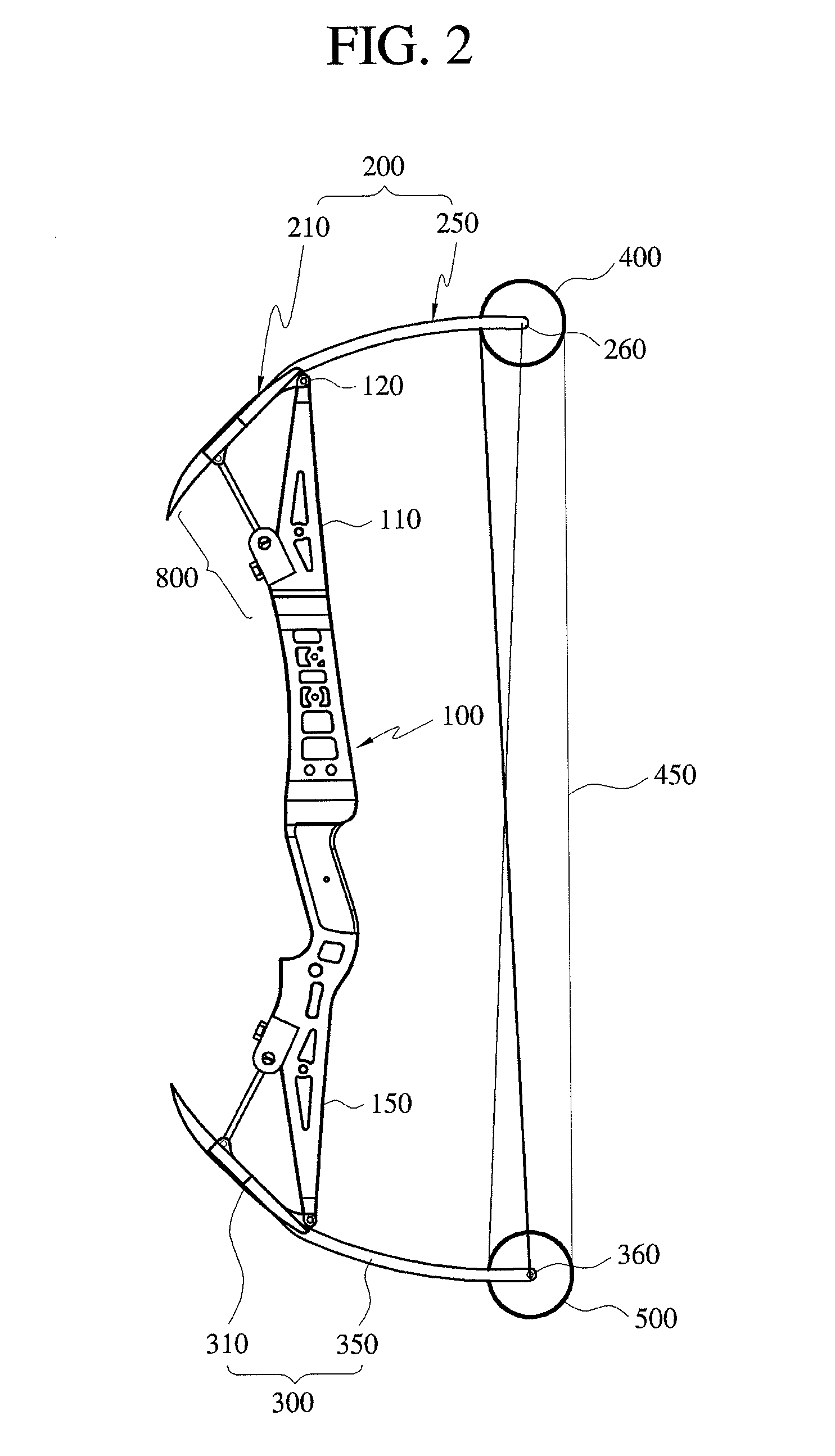
[0069]FIG. 2 is a plan view showing a compound bow according to a first embodiment of this invention. FIG. 3 is a plan view showing the compound bow of a state where tension of a bow string has been removed from the compound bow of FIG. 2. FIG. 4 is a perspective view showing a state where a limb pocket and a bow handle have been assembled in the first embodiment of this invention. FIG. 5 is a perspective view of the limb pocket in the first embodiment of this invention. FIG. 6 is a cross-sectional view of an axis of a worm wheel in the first embodiment of this invention. FIG. 7 is a diagram illustrating a coupling relationship between a worm and a worm wheel in the first embodiment of this invention.

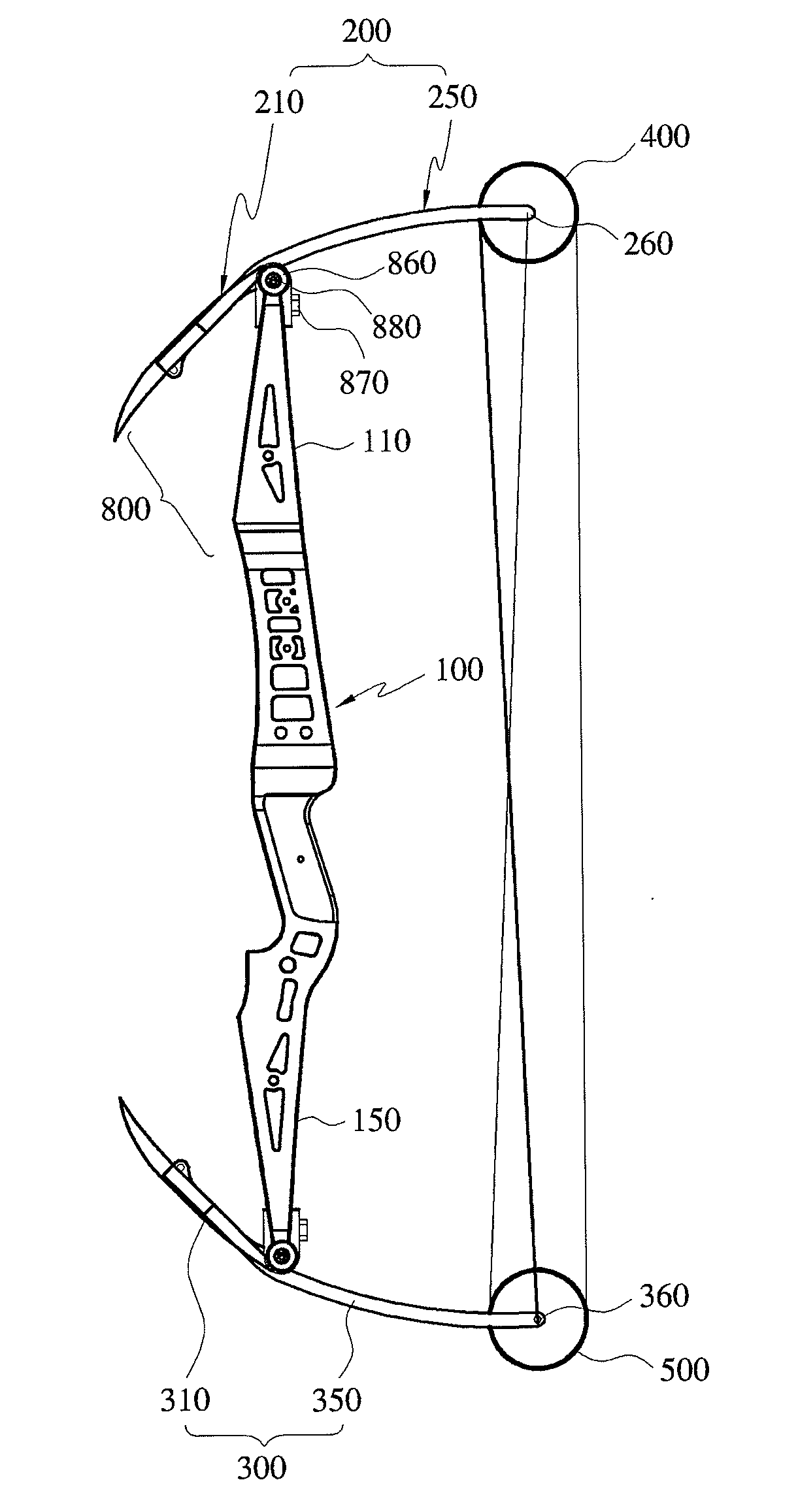
[0070]As illustrated in FIGS. 2 to 7, a compound bow according to a first embodiment of this invention includes: a bow handle 100 that a user holds with his or her hand; a pair of bow blades 200 and 300 that...

second embodiment

[0092]Next, a compound bow according to this invention will be described below with reference to the drawings.

[0093]FIG. 8 is a plan view showing a compound bow according to a second embodiment of this invention. FIG. 9 is a perspective view showing a state where a limb pocket and a bow handle have been assembled in the second embodiment of this invention. FIG. 10 is a perspective view showing a state where an axial bolt and a ratchet gear are combined in the second embodiment of this invention. FIG. 11 is a plan view of the axial bolt in the second embodiment of this invention. Blade rotating unit 600 that are respectively configured to have a connection member and a length control member in the compound bow according to the second embodiment of this invention differs from that of the first embodiment.

[0094]The connection member includes a belt 611 whose one end is combined on the front end of a limb pocket 210 that is extended forwards from the bow handle 100, and whose other end ...

third embodiment

[0114]A method of using the compound bow according to the present invention having the above-described structure will be described below in more detail. Oil has been filled in the cylinder 610a in a state where a certain tension has been applied to the bow string 450 so that a user can launch an arrow at normal times. In the case of intending to increase tension of the bow string 450 in this state, the hydraulic oil pump 640a including oil is made to operate so that oil is supplied into the cylinder 610a to thus increase pressure in the cylinder 610a. Accordingly, the bow blade 200a is made to rotate in a direction where a piston rod 630a increases distance between the pulleys 400 and 500, to thereby increase tension of the bow string 450.

[0115]In contrary, in the case of decreasing or removing tension of the bow string 450 in order to dismantle the compound bow, oil is made to drain from the cylinder 610a in order to decrease pressure in the cylinder 610a. Accordingly, the bow blad...


PUM


Abstract

A compound bow comprises a bow handle that a user holds with his or her hand. A pair of bow blades are combined with both ends of the bow handle, of which at least one bow blade is rotatably combined with the bow handle. A pair of pulleys are rotatably combined with respective rear ends of the pair of the bow blades so as to rotate around a rotating axis of each pulley. A bow string extends between the pair of pulleys and is pulled for discharge of an arrow. A blade rotating unit rotates the bow blade and is rotatably combined with the bow handle, in order to adjust or release tension of the bow string by adjusting distance between the pair of the pulleys in the case of controlling the tension of the bow string or disjointing or repairing the bow.

Description

CROSS-REFERENCE TO RELATED APPLICATIONS AND CLAIM TO PRIORITY[0001]This application is related to application number 10-2009-00115137, filed Nov. 26, 2009, in the Republic of Korea, the disclosure of which is incorporated by reference and to which priority is claimed.FIELD OF THE INVENTION[0002]The present invention relates to a compound bow, and more particularly, to a compound bow that enables a user to easily pull a bow string when he or she pulls the bow string, and that increases a force of a discharged arrow during discharge of the arrow, without consuming a big force by using an effect of a cam or a wheel, as well as enables him or her to disjoint, repair or re-assemble the bow without special equipment, and to easily adjust tension of the bow string.BACKGROUND OF THE INVENTION[0003]In general, a compound bow enables a user to easily pull a bow string when he or she pulls the bow string, and that increases a force of a discharged arrow during discharge of the arrow, without c...

Claims


Application Information

Patent Timeline
Patent Type & Authority Applications(United States)
IPC IPC(8): F41B5/10
CPCF41B5/10F41B5/0094F41B5/14
Inventor EEE, CHANG HO
Owner EEE CHANG HO
Why Eureka
Try Eureka