Device and method for controlling an electromagnetic valve

a technology of electromagnetic valve and electromagnetic field, which is applied in the direction of electrical control, water supply installation, machines/engines, etc., can solve the problems of difficult exact metering of liquid, very high thermal load of valves, etc., and achieve the effect of avoiding undesired or even unacceptable heating of valves, avoiding damage to valves early and avoiding heat loss

Active Publication Date: 2011-05-26
ROBERT BOSCH GMBH
View PDF9 Cites 10 Cited by
  • Summary
  • Abstract
  • Description
  • Claims
  • Application Information

AI Technical Summary

Benefits of technology

[0003]The device according to the present invention makes reliable operation and diagnosis of an electromagnetic valve possible. In particular, the influence of temperature on the dosing may be taken into consideration and possible damage to the valve may be detected early and avoided. Furthermore, the movements of the valve, in particular the valve needle, may be determined and used for more exact control of the valve and accordingly exact dosing of the liquid. These advantages result from determining the valve's temperature, which is considered in the activation of and / or the current feed to the valve.
[0004]It is advantageous in particular if the current feed is temperature-optimized. This makes it possible to avoid an undesired or even unacceptable heating of the valve. In connection with the temperature-optimized current feed, it is provided that the current is fed in such a way that the heating of the valve is as low as possible. It is accepted that the dosing characteristics of the valve are worsened. In particular, the opening and closing of the valve may be delayed.
[0005]It is advantageous in particular if these changes caused by the temperature-optimized activation are reduced by a changed activation. Thus a delayed opening may be compensated by a longer current feed.
[0006]An analysis of the current flowing through the valve and the voltage present at the valve makes it possible to perform a simple resistance measurement and accordingly detect the temperature.

Problems solved by technology

In particular when used in an exhaust gas aftertreatment system, these valves are exposed to a very high thermal load.
This makes the exact metering of the liquid to be dosed more difficult, since the dosing quantity also changes when the temperature changes.

Method used


Image

  • Device and method for controlling an electromagnetic valve
  • Device and method for controlling an electromagnetic valve
  • Device and method for controlling an electromagnetic valve

Examples


Embodiment Construction

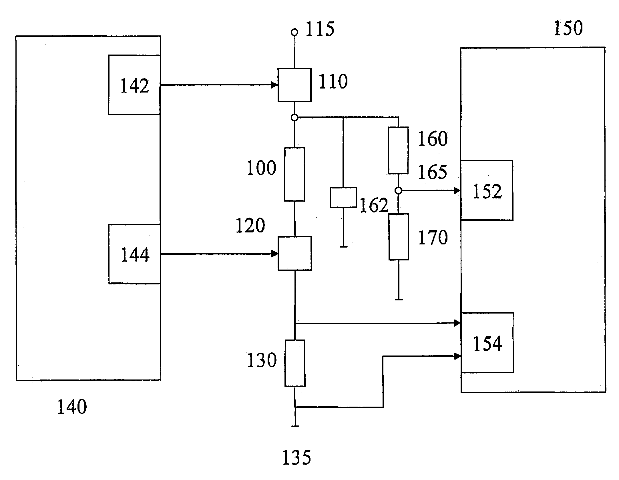
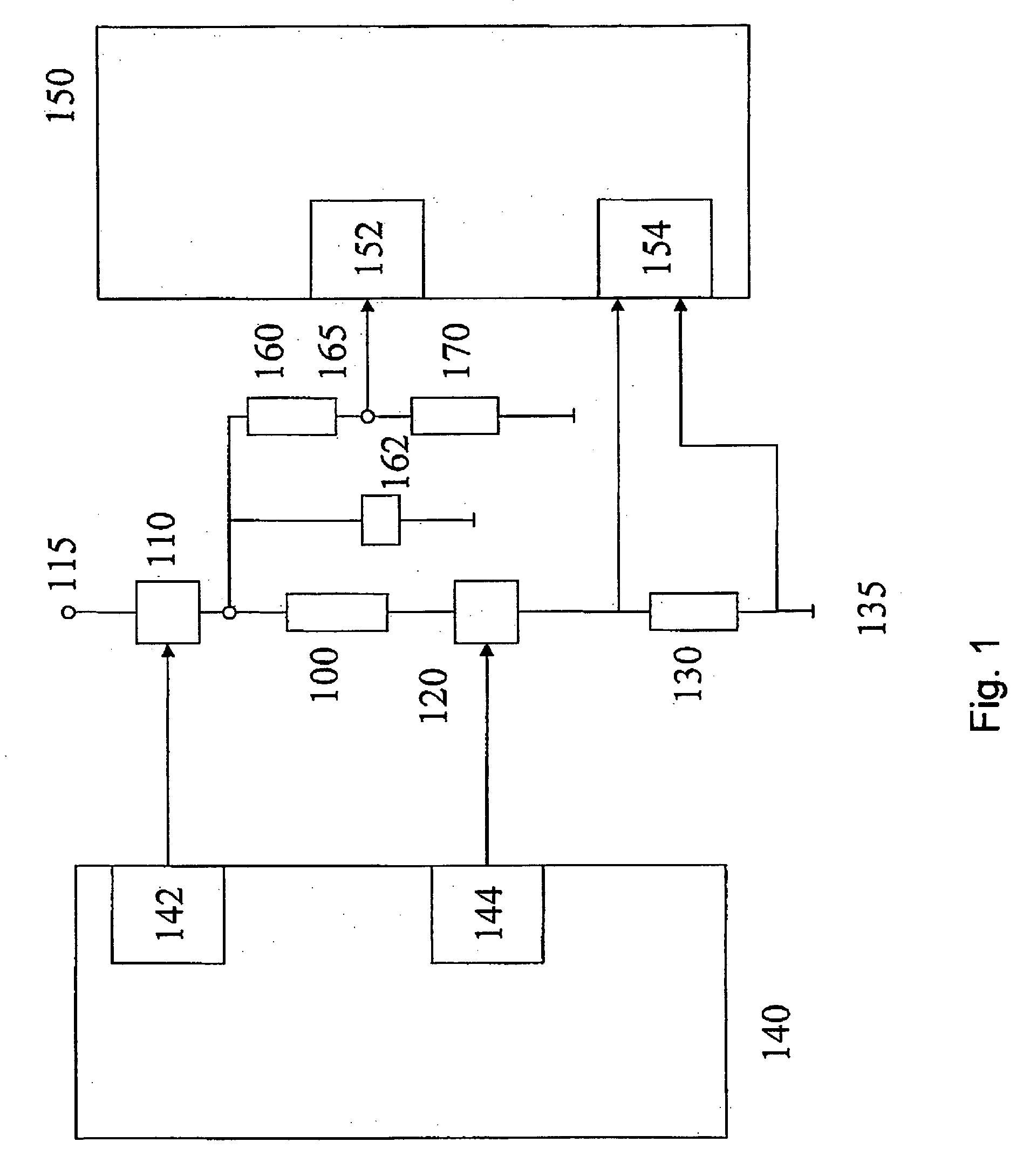
[0011]The essential elements of a device for controlling an electromagnetic valve are shown in FIG. 1. The valve is denoted as 100. This valve is connected to a first terminal of a voltage supply 115 via first switching means 110, also described as a high-side switch. In addition, valve 100 is connected to a second terminal 135 of the voltage supply via second switching means 120, also described as a low-side switch, and current sensing means 130.

[0012]First switching means 110 are activated by a current controller 142 and the second switching means are activated by a metering controller 144. Current controller 142 and metering controller 144 are the principal elements of a controller 140. In principle, it may also be provided that the metering controller activates first switching means 110 and the current controller activates second switching means 120. In this case, the positioning of various additional elements, such as current sensing means 130 and freewheeling means and / or quen...


PUM


Abstract

In a method for controlling an electromagnetic valve, the temperature of the valve is detected, and activation of and / or the current feed to the valve are performed as a function of the temperature of the valve.

Description

BACKGROUND INFORMATION[0001]The present invention relates to a method and a device for controlling an electromagnetic valve, in particular in a motor vehicle.[0002]Electromagnetic valves are customarily used for dosing liquids, for example fuel and / or liquids used in connection with an exhaust gas aftertreatment, for example an aqueous urea solution. In particular when used in an exhaust gas aftertreatment system, these valves are exposed to a very high thermal load. This makes the exact metering of the liquid to be dosed more difficult, since the dosing quantity also changes when the temperature changes. If no diagnosis is provided, the state of the valve is unclear. Thus, the control unit normally has no information as to whether the valve is overloaded, is blocked, or if the quantity emitted corresponds to the desired quantity of liquid to be dosed. It is customarily provided that these conditions are estimated and this estimation is used to provide a corresponding control that c...

Claims


Application Information

Patent Timeline
Patent Type & Authority Applications(United States)
IPC IPC(8): F17D1/00F16K31/02
CPCF01N3/206F01N3/208F01N11/005F01N2550/05F01N2610/02F01N2610/03Y02T10/24F02D41/20F02D2041/2051F02D2041/2055F02D2041/2058F02D2041/2065Y02T10/47F01N2610/14Y02T10/12Y02T10/40Y10T137/0318
Inventor KALUZA, JANKLEINKNECHT, HORST
Owner ROBERT BOSCH GMBH
Why Eureka
Try Eureka