Stabilization of unstable space debris

a technology of unstable space debris and stabilization, which is applied in the field of stabilization of unstable space debris, can solve the problems of space debris threatening the ability to safely operate spacecraft in earth orbit, affecting and reducing so as to ensure the safety of spacecraft operation and reduce the useful life of spacecra

Inactive Publication Date: 2011-05-26
POULOS AIR & SPACE
View PDF10 Cites 41 Cited by
  • Summary
  • Abstract
  • Description
  • Claims
  • Application Information

AI Technical Summary

Benefits of technology

[0003]Space debris is a growing issue threatening the ability to safely operate spacecraft in Earth Orbit. Because space debris is not under active positive control, it represents a collision hazard to spacecraft. Currently, it is the spacecraft that is acted upon (e.g., maneuvered to avoid a collision). However, maneuvering to avoid debris is costly. It artificially decreases the useful life of the spacecraft (e.g., satellites or payloads) by expending fuel that is intended for other mission essential events.

Problems solved by technology

Space debris is a growing issue threatening the ability to safely operate spacecraft in Earth Orbit.
Because space debris is not under active positive control, it represents a collision hazard to spacecraft.
However, maneuvering to avoid debris is costly.
It artificially decreases the useful life of the spacecraft (e.g., satellites or payloads) by expending fuel that is intended for other mission essential events.
While the capability to rendezvous with space objects and conduct proximity operations in the vicinity of those objects has been demonstrated, there is currently no demonstrated means of stabilizing unstable space debris so that (a) the unstable space debris may be captured for de-orbit or (b) the orbital parameters of the debris may be changed to either maneuver the debris into a safe orbit or for de-orbit.

Method used


Image

  • Stabilization of unstable space debris
  • Stabilization of unstable space debris
  • Stabilization of unstable space debris

Examples


example 1

Method of Stabilizing Unstable Space Debris via Pneumatic Impingement

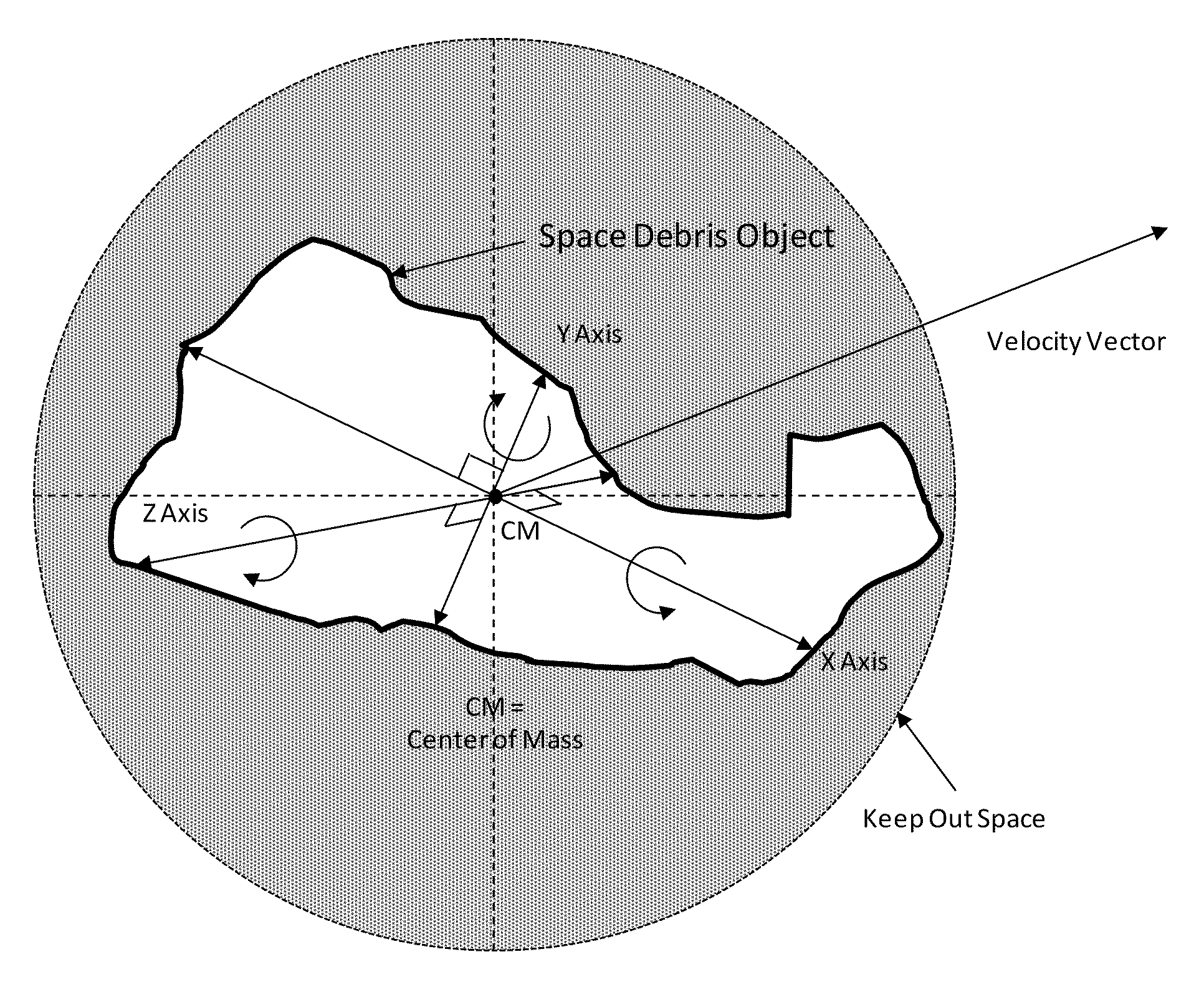
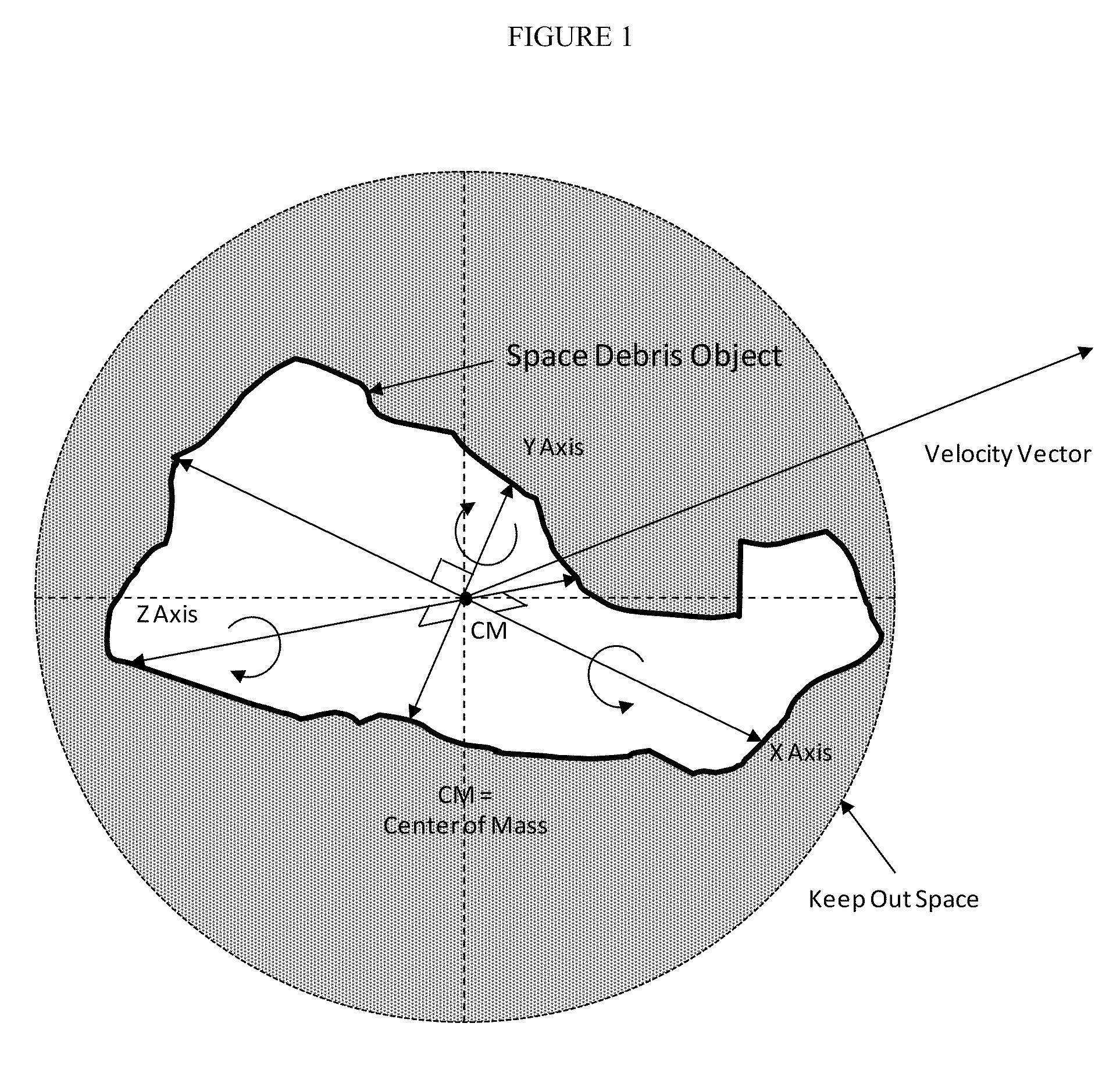
[0124]There are several hundred non-functioning rocket bodies (r / b) and spacecraft (s / c) in Low Earth Orbit (LEO) between 600 kilometers (km) and 2,000 km altitude which create the potential for an impact that will increase the population of space debris in LEO. In order to reduce the probability of collision, a decision is made to capture and de-orbit several of these rocket bodies and spacecraft each year. After surveying the non-functioning spacecraft and rocket bodies in that altitude band, it is determined that Rocket Body One has the highest potential for collision and so it becomes the highest priority to de-orbit. It is also determined that the attitude and orientation of Rocket Body One is unstable, that it exhibits characteristics of rotational motion in three axes, and that the rotational motion is coupled between all three axes so that the rotational motion appears to be random. Rocket Body One must be ...

example 2

Method of Stabilizing Unstable Space Debris and Capturing the Stabilized Space Debris

[0132]There are several hundred non-functioning rocket bodies (r / b) and spacecraft (s / c) in Low Earth Orbit (LEO) between 600 kilometers (km) and 2,000 km altitude which create the potential for an impact that will increase the population of space debris in LEO. In order to reduce the probability of collision, a decision is made to capture and de-orbit several of these rocket bodies and spacecraft each year. After surveying the non-functioning spacecraft and rocket bodies in that altitude band, it is determined that Rocket Body Two has a high potential for collision and so it becomes a high priority to de-orbit. It is also determined that the attitude and orientation of Rocket Body Two is unstable, that it exhibits characteristics of rotational motion in three axes, and that the rotational motion is coupled between all three axes so that the rotational motion appears to be random. Rocket Body Two mu...

example 3

Method of Stabilizing Unstable Space Debris and Altering the Orbital Path the Stabilized Space Debris

[0142]There are several hundred non-functioning rocket bodies (r / b) and spacecraft (s / c) in Low Earth Orbit (LEO) between 600 kilometers (km) and 2,000 km altitude which create the potential for an impact that will increase the population of space debris in LEO. In order to reduce the probability of collision, a decision is made to capture and de-orbit several of these rocket bodies and spacecraft each year. After surveying the non-functioning spacecraft and rocket bodies in that altitude band, it is determined that Spacecraft One has a high potential for collision and so it becomes a high priority to de-orbit. It is also determined that the attitude and orientation of Spacecraft One is unstable, that it exhibits characteristics of rotational motion in three axes, and that the rotational motion is coupled between all three axes so that the rotational motion appears to be random. Spac...


PUM


Abstract

Disclosed herein, in certain embodiments, is a method of altering the stability of unstable space debris. In some embodiments, the method further comprises changing the orbit of the unstable space debris.

Description

CROSS-REFERENCE[0001]This application claims priority from U.S. Provisional Patent Application 61 / 264,386, filed Nov. 25, 2009, which is incorporated herein by reference in its entirety.BACKGROUND OF THE INVENTION[0002]There are over 20,000 pieces of man-made (artificially introduced) space debris currently being tracked in orbit around the Earth. Some space debris is found in Low Earth Orbit (LEO) (e.g., at altitudes between 200 km and 2,000 km). Some space debris is found in Medium Earth Orbit (MEO) (e.g., at altitudes between 2,000 km and 35,586 km). Some space debris is found in Geosynchronous Earth Orbit (GEO) (e.g., at altitude of 35,786 km±200 km). Some space debris is found at altitudes in excess of the GEO belt. Much of the space debris (approximately 40%) is concentrated in stable circular or elliptical orbits between 200 km and 2,000 km.SUMMARY OF THE INVENTION[0003]Space debris is a growing issue threatening the ability to safely operate spacecraft in Earth Orbit. Becaus...

Claims


Application Information

Patent Timeline
Patent Type & Authority Applications(United States)
IPC IPC(8): B64G1/26
CPCB64G1/646B64G1/1078
Inventor POULOS, DENNIS
Owner POULOS AIR & SPACE
Why Eureka
Try Eureka