Automatic current limit adjustment for linear and switching regulators

a current limit and switching regulator technology, applied in the direction of electric variable regulation, power conversion systems, instruments, etc., can solve problems such as startup or operation failures, imposing input current limitations on pmu, and undesired behavior, so as to avoid undesired interruption of input power flow

Active Publication Date: 2011-05-26
DIALOG SEMICONDUCTOR GMBH
View PDF15 Cites 10 Cited by
  • Summary
  • Abstract
  • Description
  • Claims
  • Application Information

AI Technical Summary

Benefits of technology

[0015]A principal object of the present invention is to achieve a powe

Problems solved by technology

This is generally done imposing an input current limitation on the PMU according to the kind of power source connected to it.
This prior art scheme shows an undesired behavior in presence of high resistive interconnect (high Rcable due to long interconnection cable) or low budgetary power source (high source output resistance Rout).
This behavior is obviously unacceptable: even a load current generating an input current below the specified limit can lead to an interruption of the pow

Method used


Image

  • Automatic current limit adjustment for linear and switching regulators
  • Automatic current limit adjustment for linear and switching regulators
  • Automatic current limit adjustment for linear and switching regulators

Examples


Embodiment Construction

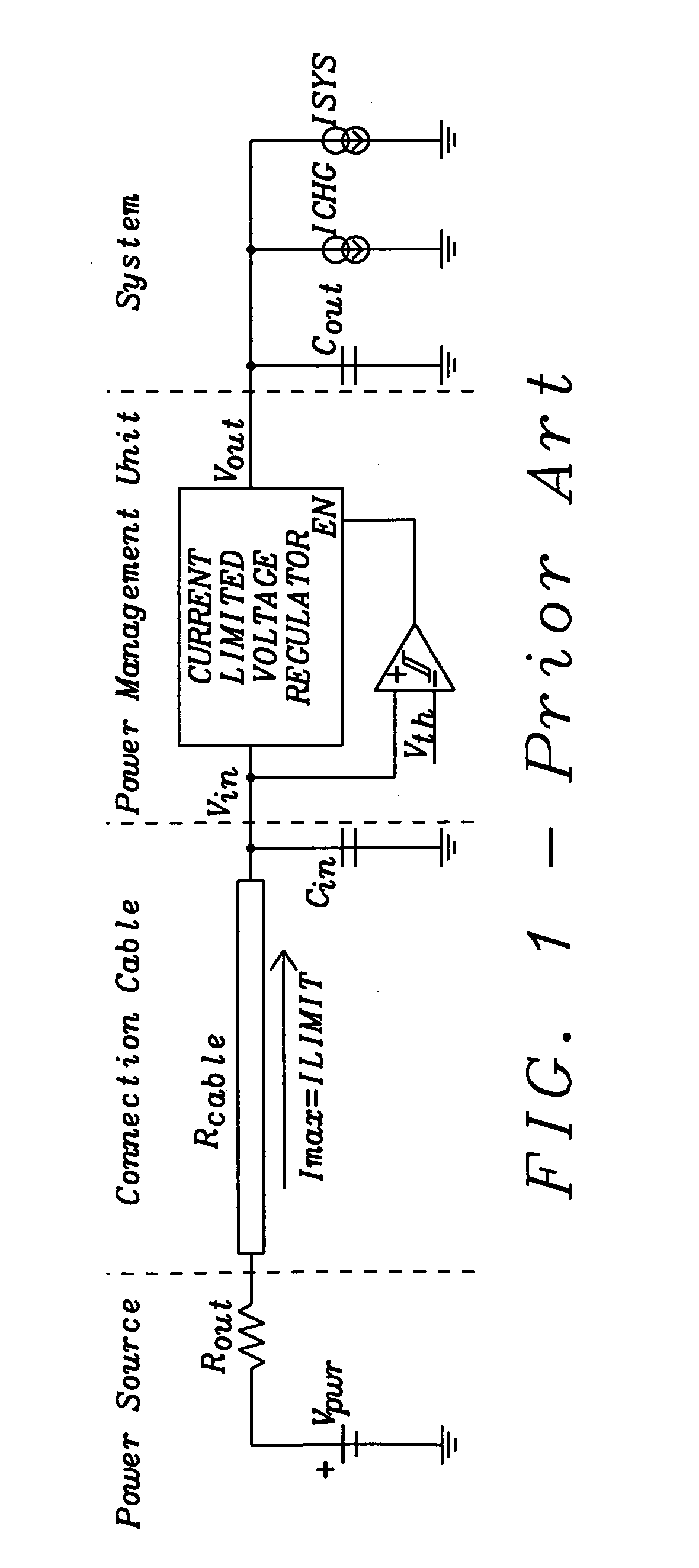
[0028]The preferred embodiments disclose methods and systems to achieve a fully functional power management unit (i.e. a means of transferring power from a power source to a system / battery) even in presence of power sources having low quality / high-output-resistance and / or high resistive cables.

[0029]The preferred embodiments of the present invention discussed refer to a Power Management Unit (PMU) of a portable system, in which an input current limited DC-DC converter has to provide power to the needs of both a battery charger and a system load. These particular implementations should serve however only for explanation purposes and it is not intended to limit the field of application of the invention.

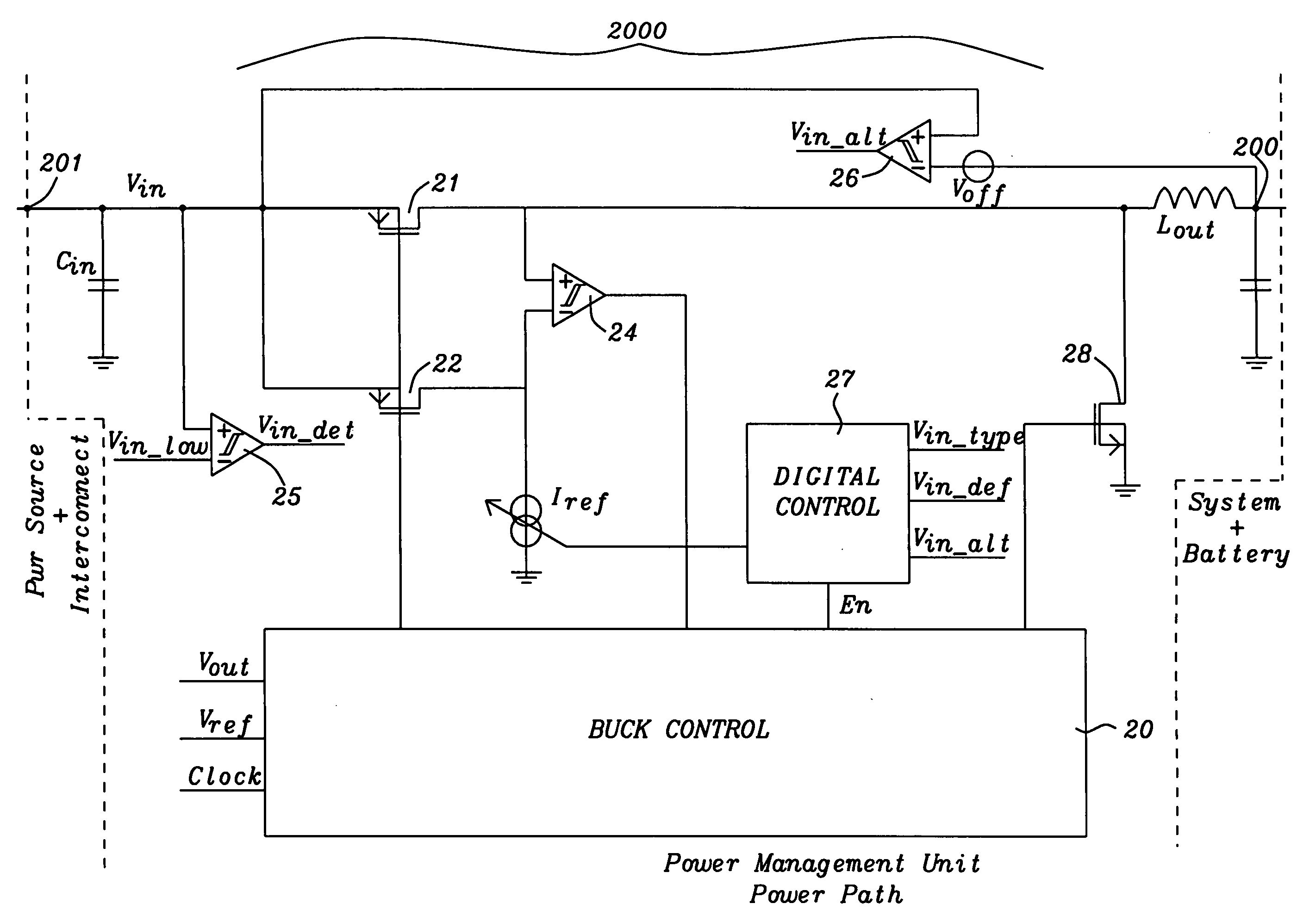
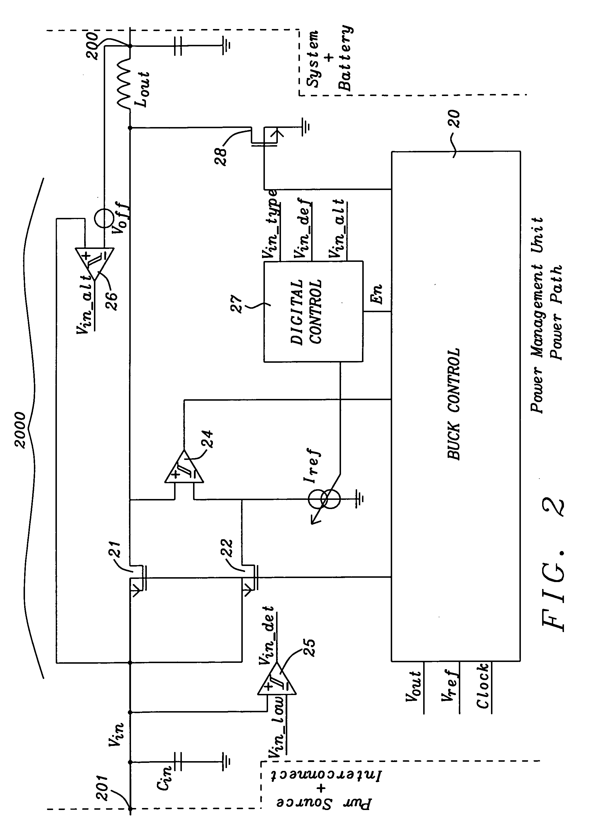
[0030]The dynamic current limit control scheme of the present invention is depicted in FIG. 2. FIG. 2 shows a power path of a power management unit 2000. In a preferred embodiment of the invention a current limited buck converter is used to transfer the power from the power source to th...


PUM


Abstract

Circuits and methods for dynamic adjustment of the current limit of a power management unit to avoid unwanted automatic interruption of the power flow have been disclosed. The power management unit is automatically adjusted to the output resistance of a power source (including interconnect resistance). The invention maximizes the time and hence the power transferred from a power management unit to the system (including the battery, in case of battery operated systems). The input current is reduced thus increasing the input voltage in case of a high voltage drop across the internal resistance including interconnections between power source and power management unit.

Description

BACKGROUND OF THE INVENTION[0001](1) Field of the Invention[0002]This invention relates generally to the field of supply voltage generators (linear regulators or DC-DC converters) and more specifically to those equipped with an input current limit control mechanism.[0003](2) Description of the Prior Art[0004]Every modern integrated power management system has to be able to accommodate for a broad range of voltage sources (USB, 5V wall adapter, Firewire, automotive battery). Each of them comes in a variety of output specs, in particular regarding nominal output voltage and maximum current capability. The power management unit (PMU) has to guarantee that in every circumstance the load seen by the power source is within the specified ranges. This is generally done imposing an input current limitation on the PMU according to the kind of power source connected to it.[0005]In FIG. 1 prior art a generic schematic of such a power management system is shown. The power source is represented b...

Claims


Application Information

Patent Timeline
IPC IPC(8): G05F1/569G05F1/46
CPCH02M3/157H02M3/156
Inventor SCALDAFERRI, STEFANOMARSCHALKOWSKI, ERICWOLF, CHRISTIAN
Owner DIALOG SEMICONDUCTOR GMBH
Why Eureka
Try Eureka