Filter apparatus, filter accommodating method, exposure apparatus and method for producing device

Inactive Publication Date: 2011-05-26
NIKON CORP
View PDF3 Cites 1 Cited by
  • Summary
  • Abstract
  • Description
  • Claims
  • Application Information

AI Technical Summary

Benefits of technology

[0009]Taking the foregoing circumstances into consideration, an object of the present invention is that the filters are installed or exchanged efficiently or the filters are installed or exchanged so that the positioning of the filters can be performed with ease.
[0017]According to the above-described aspect, the first frame is moved so that the first recess and the second recess of the first protrusion / recess-formed portion of the first frame are successively engaged with the first engaging portion of the accommodating portion. By doing so, the first frame can be placed or installed in the accommodating portion efficiently or the first frame can be positioned with ease. Further, by moving the first frame in the opposite direction, it is possible to efficiently unload the first frame from the accommodating portion. Therefore, the first filter, which is held by the first frame, can be efficiently exchanged.

Problems solved by technology

It is feared that positional deviation or shift may be caused between the plurality of chemical filters, and the gas-tightness may be lowered between the chemical filters.

Method used


Image

  • Filter apparatus, filter accommodating method, exposure apparatus and method for producing device
  • Filter apparatus, filter accommodating method, exposure apparatus and method for producing device
  • Filter apparatus, filter accommodating method, exposure apparatus and method for producing device

Examples


first embodiment

[0030]A first embodiment of the present invention will be explained below with reference to FIGS. 1 to 8.

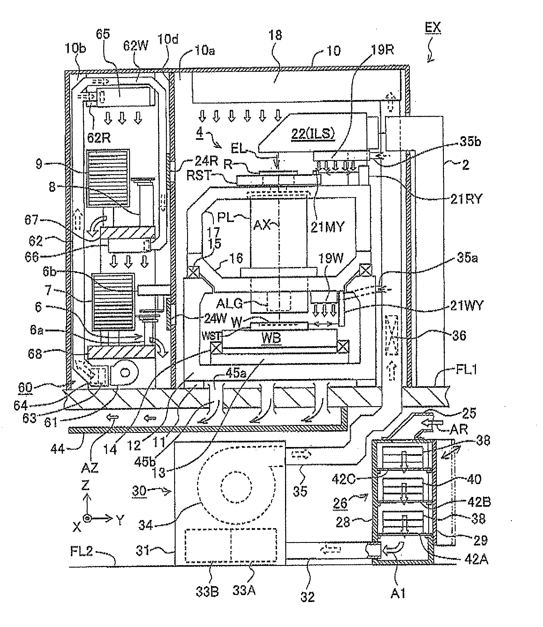
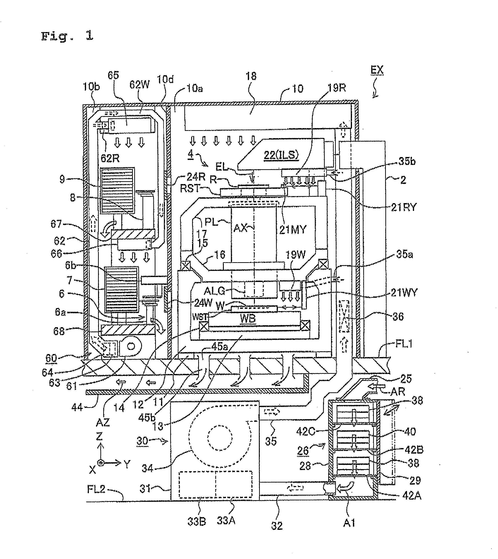
[0031]FIG. 1 shows, with partial cutaway, an exposure apparatus EX according to this embodiment which is of the scanning exposure type and is constructed of a scanning stepper. With reference to FIG. 1, the exposure apparatus EX includes a light source section 2 which generates an exposure light (illumination light or illumination light beam for the exposure) EL, an illumination optical system ILS which illuminates a reticle R (mask) with the exposure light EL, a reticle stage RST which is movable while holding the reticle R, and a projection optical system PL which projects an image of a pattern of the reticle R onto a surface of a wafer W (substrate) coated with a photoresist (photosensitive material). The exposure apparatus EX further includes a wafer stage WST which is movable while holding the wafer W, other driving mechanisms, sensors, etc., a reticle library 9 which stores...

second embodiment

[0130]Next, a second embodiment of the present invention will be explained with reference to FIGS. 9 to 11. In this embodiment, the shapes of the guide grooves on the side surfaces (protrusion / recess-formed portions) of the frame of the filter box are changed; and the other portions are the same as or equivalent to those of the first embodiment. In the following description, the components or parts, which correspond to those shown in FIGS. 4, 5, and 6, are designated by the same reference numerals in FIGS. 9, 10, and 11, any detailed explanation of which will be omitted.

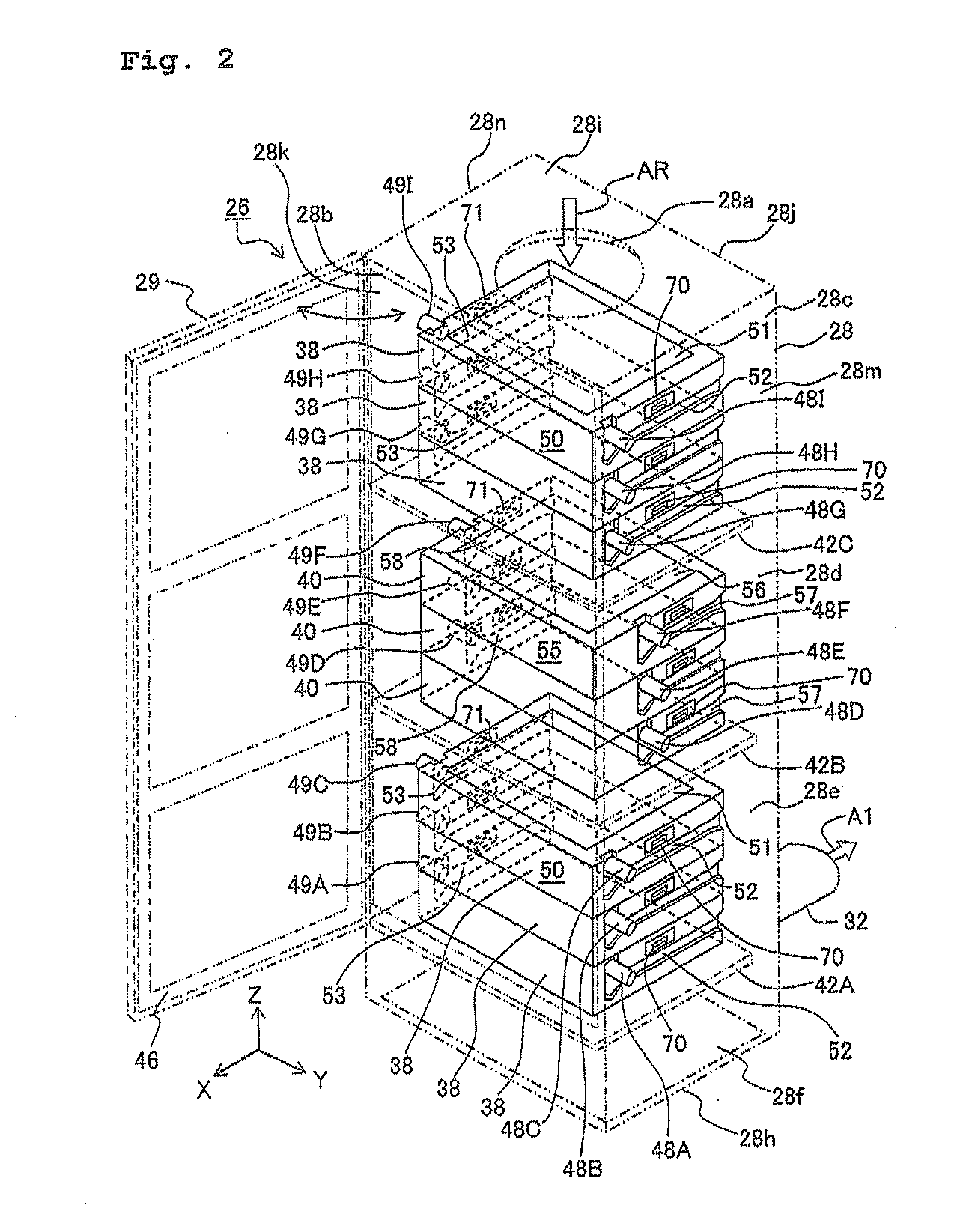
[0131]FIG. 9A shows a perspective view illustrating a filter box 38A which holds the chemical filter 51, and FIG. 9C shows a perspective view illustrating a filter box 40A which holds the chemical filter 56. The filter boxes 38A, 40A can be installed in the casing 28, instead of the filter boxes 38, 40 shown in FIG. 2 respectively.

[0132]As shown in FIG. 9A, guide grooves (protrusion / recess-formed portions) 52A, 53A a...


PUM

PropertyMeasurementUnit
Widthaaaaaaaaaa
Dimensionaaaaaaaaaa
Heightaaaaaaaaaa

Abstract

A filter apparatus which holds a chemical filter includes a frame which holds the chemical filter and which has a guide groove provided on a side surface of the frame; and a casing which accommodates the frame. The guide groove has a first groove which is communicated with a back surface of the frame, and a second groove which is communicated with the first groove and which extends from a front surface of the frame toward an upper end thereof. The casing has a shaft member which is engageable with the first groove to support the frame and which is engageable with the second groove to release the frame from being supported. It is possible to install the filter efficiently so that the filter can be positioned with ease, and to unload the filter efficiently.

Description

BACKGROUND OF THE INVENTION[0001]1. Field of the Invention[0002]The present invention relates, for example, to a filter apparatus which holds a filter or filters for removing any impurity, etc. contained in a gas, and a filter accommodating method. The present invention also relates to an exposure apparatus provided with the filter apparatus, and a device producing method for producing, for example, a semiconductor element, a liquid crystal display element, or an image pickup element by using the exposure apparatus.[0003]2. Description of the Related Art[0004]In order to obtain a high exposure accuracy (resolution, positioning accuracy, etc.) in an exposure apparatus to be used in the lithography step of producing an electronic device (microdevice) including for example a semiconductor element, it is necessary that the illumination characteristic of an illumination optical system and the imaging characteristic of a projection optical system are maintained in predetermined states; an...

Claims


Application Information

Patent Timeline
IPC IPC(8): G03B27/52B01D46/10B01D46/12B23P11/00F24F1/0073
CPCB01D53/40B01D53/44B01D53/58Y10T29/49826F24F13/28F24F2001/0096G03F7/70916B01D2257/406F24F1/0071F24F1/0073
Inventor KATSURA, KOICHIOGIWARA, TSUKASAMATSUURA, KEIJIHORITA, YOSHINARIMASUKAWA, TAKASHI
Owner NIKON CORP
Why Eureka
Try Eureka