
Energy generation apparatus and method

a technology of energy generation apparatus and method, applied in nuclear reactors, nuclear engineering, greenhouse gas reduction, etc., can solve the problems of difficult, if not impossible, and difficult to extract more energy than is used in instigate reaction, so as to avoid the destruction of the core and avoid the effect of the core destruction

Inactive Publication Date: 2011-05-26
BRILLOUIN ENERGY CORP
View PDF3 Cites 10 Cited by
  • Summary
  • Abstract
  • Description
  • Claims
  • Application Information

AI Technical Summary

Benefits of technology

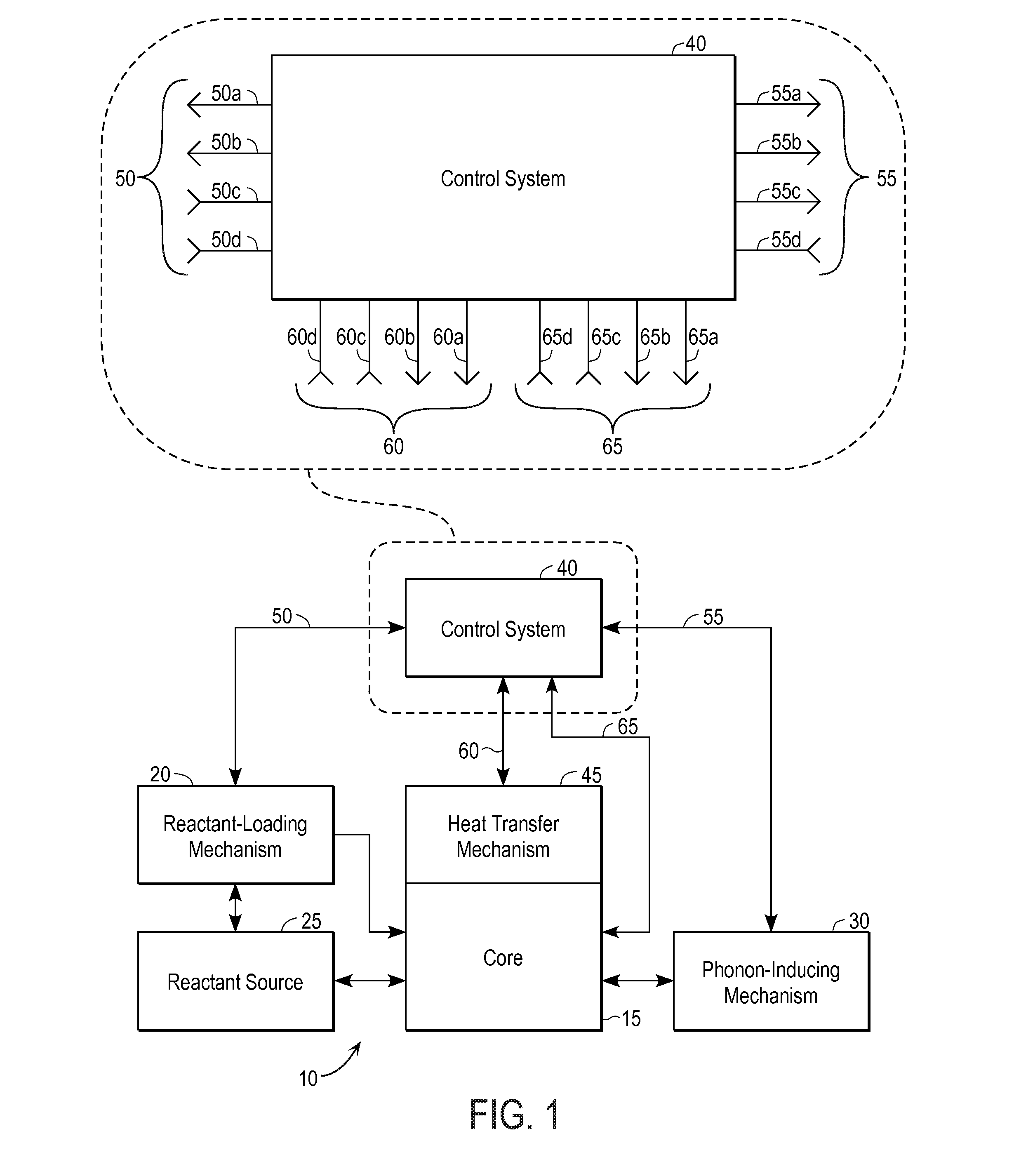
[0013]a mechanism for controlling the loading of reactants and the generation of phonons so that reactants, when introduced into said core, undergo nuclear reactions to a desired degree without destroying the core.The control system maintains the rate of phonon generation and reactant introduction at a sufficiently high level to cause a desired number of nuclear reactions to occur while ensuring that the number of nuclear reactions and their depth is limited, thereby allowing energy released due to the nuclear reactions to dissipate in a manner that substantially avoids destruction of said core.
[0017]Another aspect of the present invention is that controlled loading of the core material combined with controlled stimulation of phonon production prevents excess phonon energy build up, which leads to destruction of the core material. This will allow the core to operate for extended lengths of time making it an economically viable source of energy.
[0018]Another aspect of the present invention is that the core is preferably constructed to provide a consistent phonon density at the desired reaction points in the core material. This allows control over energy liberated with respect to time and the ability of the core material to dissipate energy to the heat transfer medium. In specific embodiments, the phonon density is controlled so that the fusion reaction occurs primarily near the surface of the core, thus preventing the type of catastrophic damage to the core that has characterized many prior art efforts to produce repeatable, sustainable energy generation.
[0020]In one aspect, apparatus for energy generation comprises: a body, referred to as the core, of a material capable of phonon propagation; a mechanism for introducing reactants into the core; a mechanism for inducing phonons in the core so that reactants, when introduced into the core, undergo nuclear reactions; and a control system, coupled to the mechanism for introducing reactants and to the mechanism for inducing phonons, for controlling the number of nuclear reactions and the depth of the nuclear reactions in the core so as to provide a desired level of energy generation while allowing energy released due to the nuclear reactions to dissipate in a manner that substantially avoids destruction of the core.
[0021]In another aspect, a method for energy generation comprises: providing a body, referred to as the core, of a material capable of phonon propagation; introducing reactants into the core; generating phonons in the core to provide energy for said reactants to undergo nuclear reaction; and controlling the rate of reactant introduction and the rate of phonon generation so as to control the number of nuclear reactions and the depth of the nuclear reactions in the core so as to provide a desired level of energy generation while allowing energy released due to the nuclear reactions to dissipate in a manner that substantially avoids destruction of the core.

Problems solved by technology

In some instances, the energy is released in an uncontrolled manner, rendering the collection of released energy problematical and expensive, possibly prohibitively so.
However, extracting more energy than is used to instigate the reaction is extremely difficult, if not impossible, due to the Bremsstrahlung phenomenon.
Another set of techniques uses magnetic confinement, although confinement for an extended period of time has problems similar to those that beset electrostatic confinement.
Another set of techniques explores impact fusion, but these attempts suffer from problems similar to those bedeviling the other hot fusion methods.
A workable theory of cold fusion does not appear to have been articulated, and attempts to produce energy using cold fusion have generally not been reproducible and, when excess energy has been generated, have been characterized by rapid destruction of the device cores in which the reactions are occurring.
Unfortunately, the first reaction creates additional phonons that cause a chain reaction that leads to the destruction of the lattice.
This approach can create excess energy because the high loading density alone leads to a system with high Hamiltonian energy in the lattice.
[George1997] describes using ultrasonically induced multi-bubble sonoluminescence to induce fusion events, although because of the gross loading the core is quickly destroyed.

Method used


Image

  • Energy generation apparatus and method
  • Energy generation apparatus and method
  • Energy generation apparatus and method

Examples


Embodiment Construction

Overview

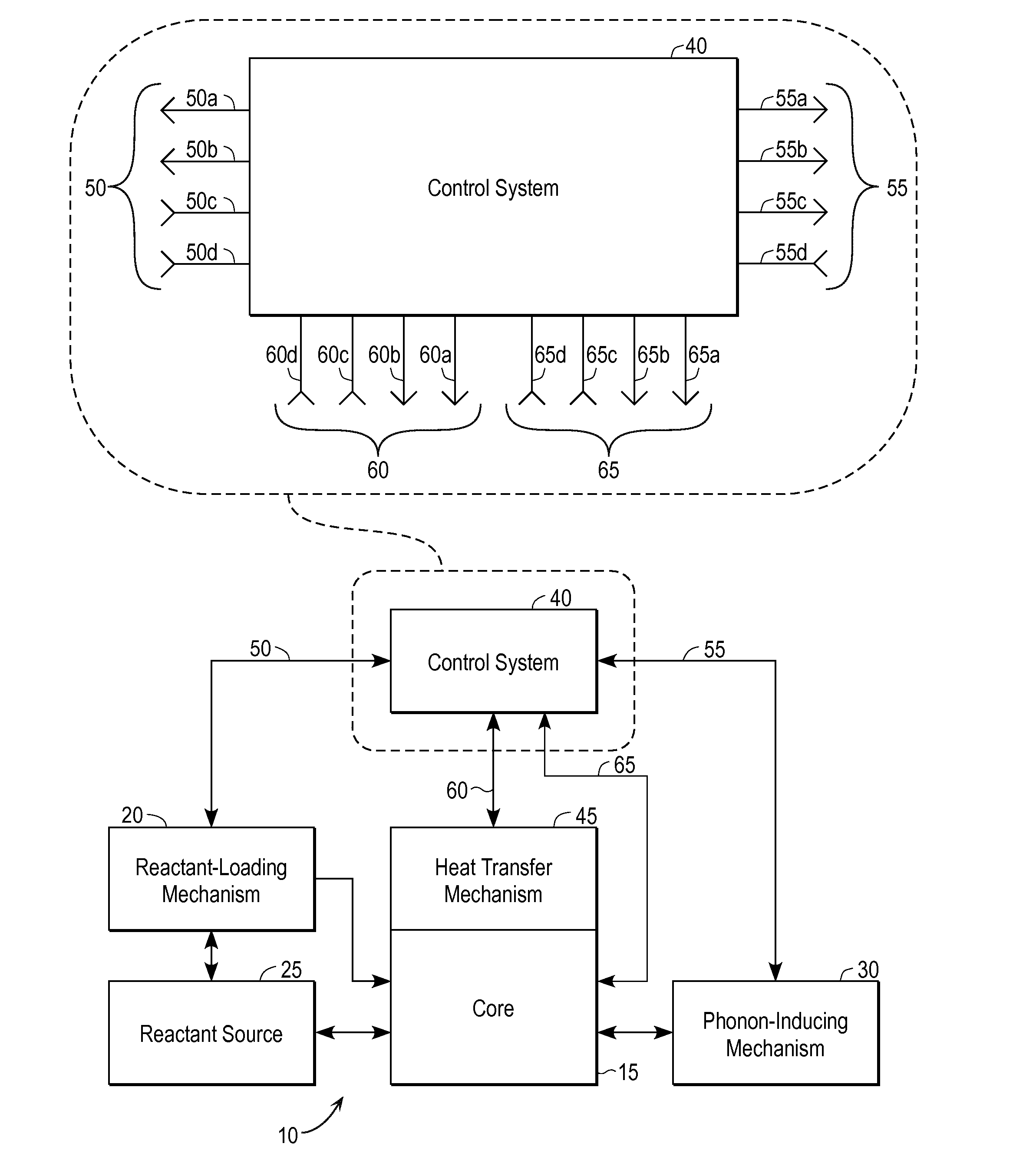
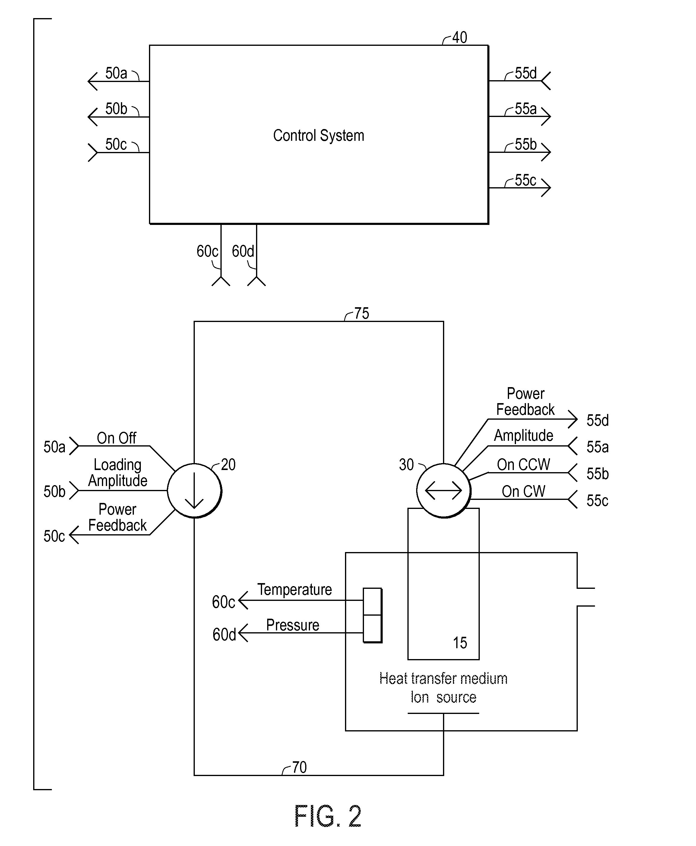
[0032]FIG. 1 is a very high level schematic representation of a Quantum Fusion reactor 10 encompassing a number of embodiments of the present invention. At the heart of the reactor is a reaction matrix or core 15 capable of phonon propagation. The general operation is for a reactant-loading mechanism 20 to load core 15 with reactant (e.g., protons) from a reactant source 25, and generate phonons in the core material using a phonon-inducing mechanism 30. A control system 40 activates and monitors reactant-loading mechanism 20 and phonon-inducing mechanism 30.

[0033]The phonon-inducing mechanism may stimulate phonons in the core directly using one or more means such as sonic / ultrasonic waves, current, or heat. Phonon energy causes displacement of the core lattice nuclei from their neutral positions. In the case where this displacement moves lattice nuclei closer together the density increases and is further increased by the presence of hydrogen nuclei (1H (protium), 2H (deuteri...


PUM


Abstract

A practical technique for inducing and controlling the fusion of nuclei within a solid lattice. A reactor includes a loading source to provide the light nuclei which are to be fused, a lattice which can absorb the light nuclei, a source of phonon energy, and a control mechanism to start and stop stimulation of phonon energy and / or the loading of reactants. The lattice transmits phonon energy sufficient to affect electron-nucleus collapse. By controlling the stimulation of phonon energy and controlling the loading of light nuclei into the lattice, energy released by the fusion reactions is allowed to dissipate before it builds to the point that it causes destruction of the reaction lattice.

Description

CROSS REFERENCE TO RELATED APPLICATIONS[0001]This application is a continuation of U.S. patent application Ser. No. 11 / 617,632, filed Dec. 28, 2006 for “Energy Generation Apparatus and Method” (Robert E. Godes), which claims priority from U.S. Provisional Patent Application No. 60 / 755,024, filed Dec. 29, 2005 for “Energy Generation Apparatus and Method” (Robert E. Godes). The entire disclosures of the above-named applications (including all attached documents) are hereby incorporated by reference for all purposes.BACKGROUND OF THE INVENTION[0002]The present invention relates generally to energy generation, and more specifically to energy generation using nuclear fusion.[0003]While there is no shortage of people desiring to produce energy through controlled fusion, the techniques can be considered to fall into two general classes, namely hot fusion and cold fusion. Hot fusion has a sound theory, and is known to work in a fashion capable of unleashing great amounts of energy in a very...

Claims


Application Information

Patent Timeline
Patent Type & Authority Applications(United States)
IPC IPC(8): G21B1/00
CPCG21B3/002Y02E30/10G21B3/00
Inventor GODES, ROBERT E.
Owner BRILLOUIN ENERGY CORP
Learn More