Outdoor transceiver connector

a transceiver and connector technology, applied in the field of cable connectors, can solve the problems of difficult access in an environmentally sealed connector, and achieve the effect of convenient use and easy removal

Active Publication Date: 2011-05-26
AMPHENOL CORP
View PDF14 Cites 93 Cited by
  • Summary
  • Abstract
  • Description
  • Claims
  • Application Information

AI Technical Summary

Benefits of technology

[0010]The inventors have recognized and appreciated that it would be desirable to provide economical, easy to use, environmentally sealed, connection systems for optical or electrical cable connectors. In one aspect, the connection system may involve optical fiber connectors that mate with pluggable transceivers. An improved interconnection system may be provided with a compliant mounting for the connector within a cable connector assembly terminating a cable. The connector may be biased, such as with a spring, away from other components of the cable connector assembly. When the cable connector assembly is attached to an adapter on a panel of an electronic assembly, force generated by a biasing member presses electrical contacts of a component coupled to the cable connector assembly against an electrical connector within the electronic assembly. For an electrical cable connector assembly, the electrical contacts may be on the electrical connector in the cable connector assembly. For an optical cable connector assembly, the force may be coupled through the optical fiber connector to a transceiver, or other component, within the electronic assembly. The biasing force may provide a mating force sufficient to ensure adequate electrical connection between the transceiver and an electrical connector within the electronic assembly. However, upon disconnection of the cable assembly, the transceiver may be readily removed.

Problems solved by technology

Thus, regardless of the form of connector in the cable connector assembly, appropriate mating can be made when the cable connector assembly is attached to an adapter, but the cable connector assembly can be removed without manipulating latches or other release mechanisms inside the cable connector assembly, which may be difficult to access in an environmentally sealed connector.

Method used


Image

  • Outdoor transceiver connector
  • Outdoor transceiver connector
  • Outdoor transceiver connector

Examples


Embodiment Construction

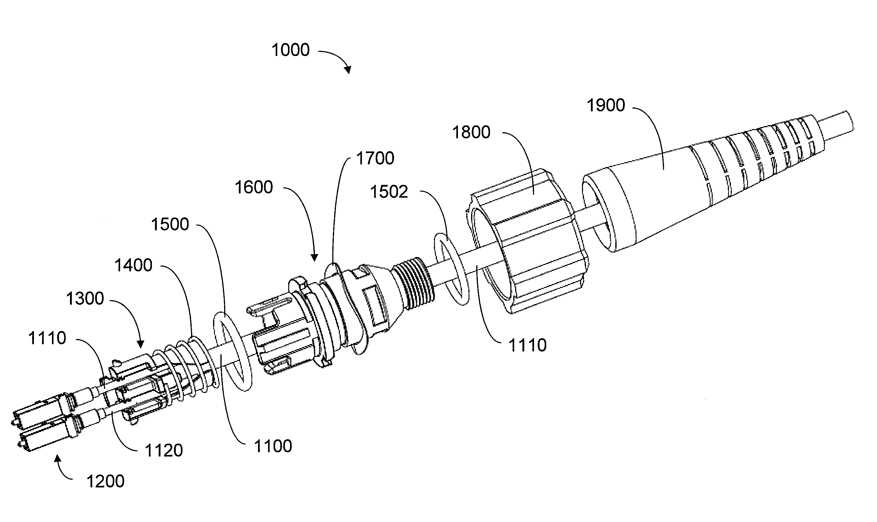
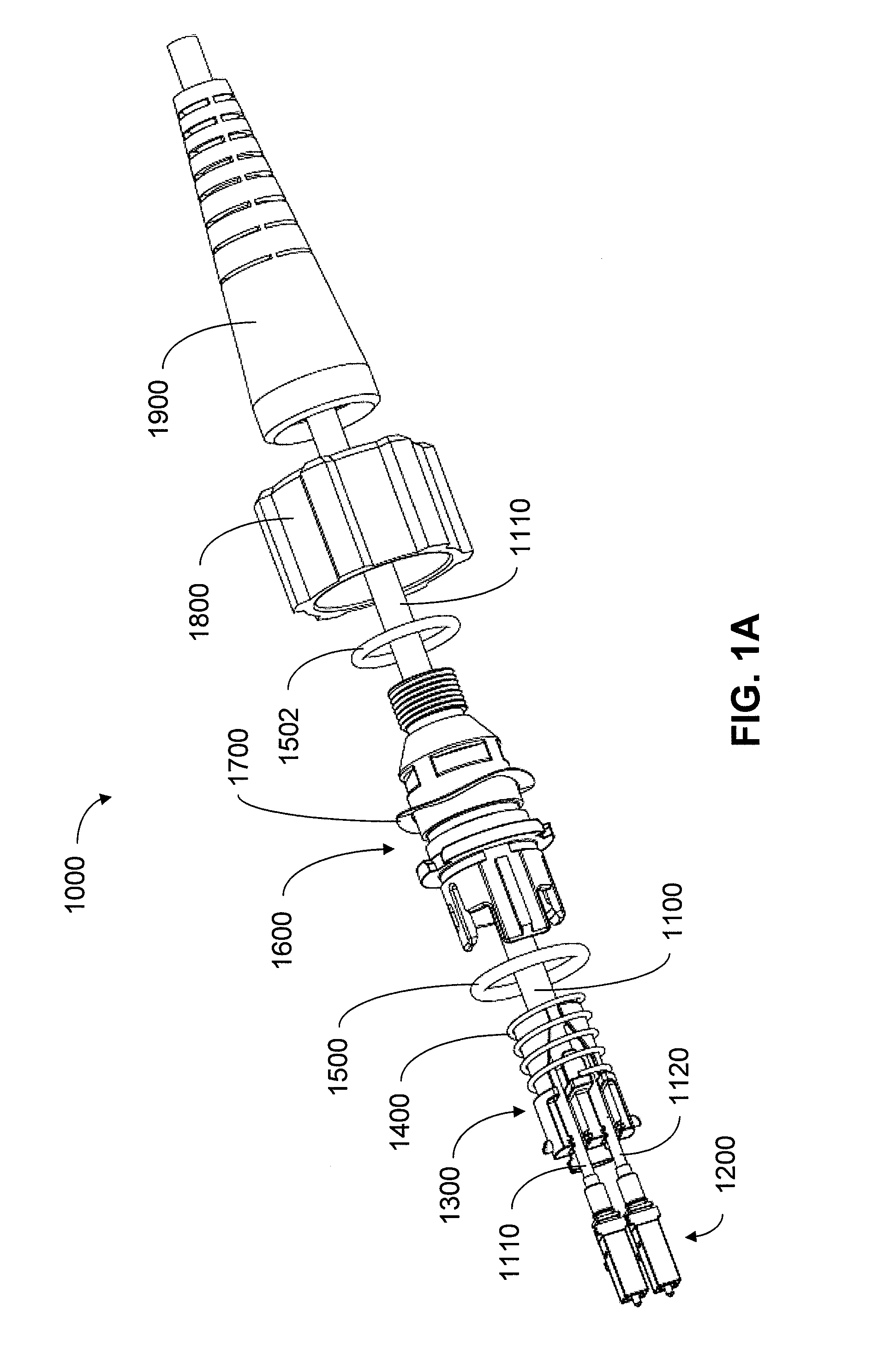
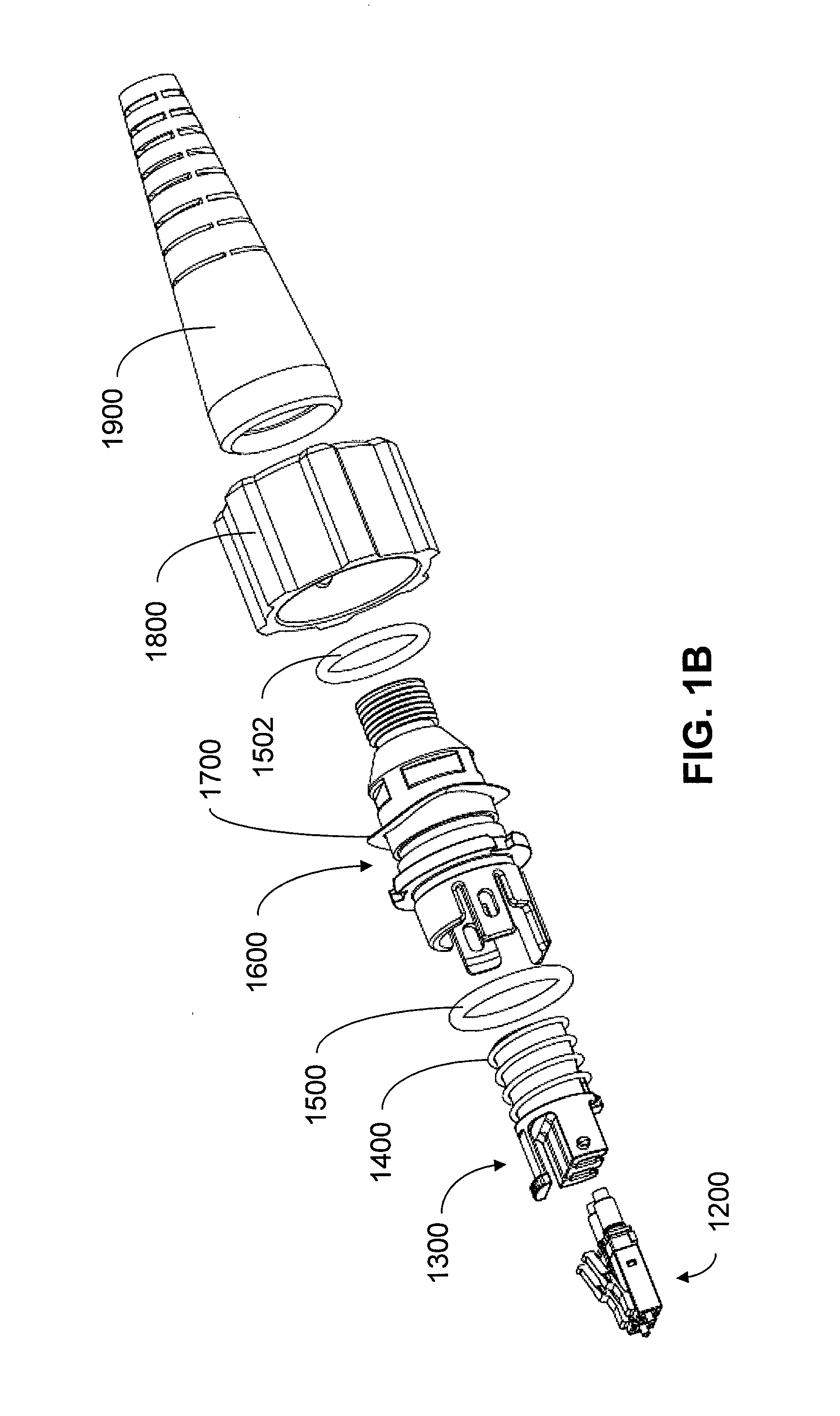
[0047]The inventors have recognized and appreciated that an improved cable connector assembly may be provided that is particularly useful in a distribution network, such as one distributing digital information to homes or other geographically dispersed locations. The connector assembly is suited for use in networks in which an interface between an optical or electrical network and an electronic assembly is made outdoors or in other settings in which environmental protection is desired.

[0048]Ease of use may be provided by generating within the cable connector assembly a force when the cable connector assembly is attached to an adapter of an electronic assembly, such as when the cable connector assembly is connected to an exterior panel of an electronic assembly. The force may be sufficient to ensure a reliable electrical connection between an electrical connector within the electronic assembly and a component that is coupled to the cable connector assembly. For a cable connector asse...


PUM


Abstract

A cable connector assembly for outdoor connection to transceivers. Electrical connection between a component of the cable connector assembly and a connector inside an electronic assembly to which the cable connector assembly is attached is made through a force generated by a biasing member within the cable connector assembly. The biasing member may generate the force as the cable connector assembly is attached to an adapter. Once the cable connector assembly is disengaged from the adapter, the force is released, allowing easy removal of the cable connector assembly, without the need to release a latch. In an environmentally sealed connector in which access to a release mechanism may be restricted, such a structure provides ease of use for either electrical or optical connectors. For optical cable connector assemblies, the optical cable connector may be coupled to a transceiver such that biasing force generated within the cable connector assembly holds the transceiver in a mating relationship with a connector within an electronic assembly but can be easily removed.

Description

BACKGROUND OF INVENTION[0001]1. Field of Invention[0002]Aspects described herein relate generally to cable connectors, including those for fiber optic transceivers, and more specifically to environmentally sealed connections for cables.[0003]2. Discussion of Related Art[0004]Modern life is full of devices that process information in digital form. Computers share digital information over the Internet or other computer networks. Information, such as radio and television signals, that in the past was communicated as analog signals is now frequently digitized and communicated over networks. For example, many homes have a high speed digital connection to a cable company or other service provider.[0005]The increased use of digital information has created a need for reliable interconnection systems that can connect devices and networks that generate or consume digital information. One form of interconnection system employs optical fiber for transmission of digital information. Large amount...

Claims


Application Information

Patent Timeline
Patent Type & Authority Applications(United States)
IPC IPC(8): G02B6/38H01R13/52G02B6/36
CPCG02B6/3816G02B6/3821H01R13/6315H01R13/516H01R13/622G02B6/4292G02B6/3891G02B6/3893G02B6/4284
Inventor BELSAN, MICHAELNGUYEN, ANH NGOCBALTRUKONIS, DARIJUS
Owner AMPHENOL CORP
Why Eureka
Try Eureka