
Deployment mechanism and method for overboard pump

a deployment mechanism and pump technology, applied in the direction of positive displacement liquid engine, valve construction, liquid fuel engine, etc., can solve the problems of not showing a compact deployment mechanism for an overboard pump, significant time and cost involved in the installation of the scaffolding, and requiring considerable engineering costs

Inactive Publication Date: 2011-05-26
S & N PUMP
View PDF9 Cites 4 Cited by
  • Summary
  • Abstract
  • Description
  • Claims
  • Application Information

AI Technical Summary

Benefits of technology

One possible object of the present invention is to provide an improved deployment system and method for deploying the overboard pump over the side of the rig or vessel.

Problems solved by technology

The additional deck and / or scaffolding must be added to the offshore rig at the shipyard and may require considerable engineering costs.
Significant time and cost is involved in installing the scaffolding.
The above cited art does not show a compact deployment mechanism for an overboard pump for use over the side of an offshore rig, wherein the pump is raised and lowered utilizing a hose reel, which avoids the problem of installing scaffolding on the side of the offshore vessel or the need of mounting system above the service deck.

Method used


Image

  • Deployment mechanism and method for overboard pump
  • Deployment mechanism and method for overboard pump
  • Deployment mechanism and method for overboard pump

Examples


Embodiment Construction

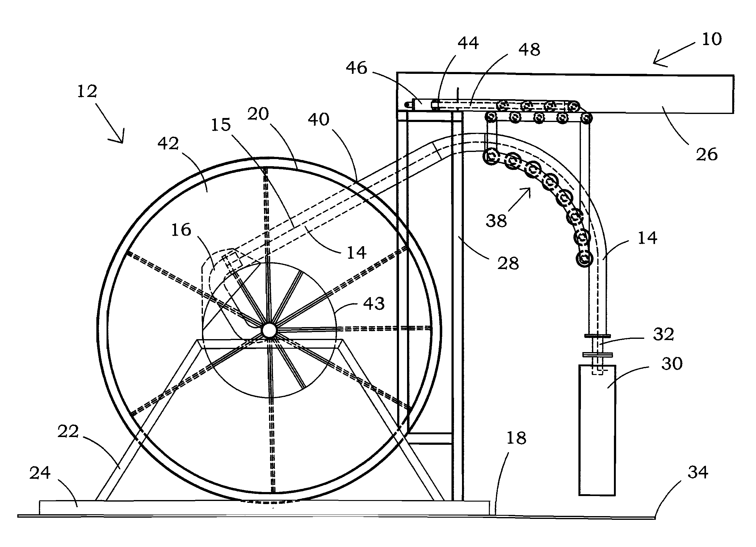
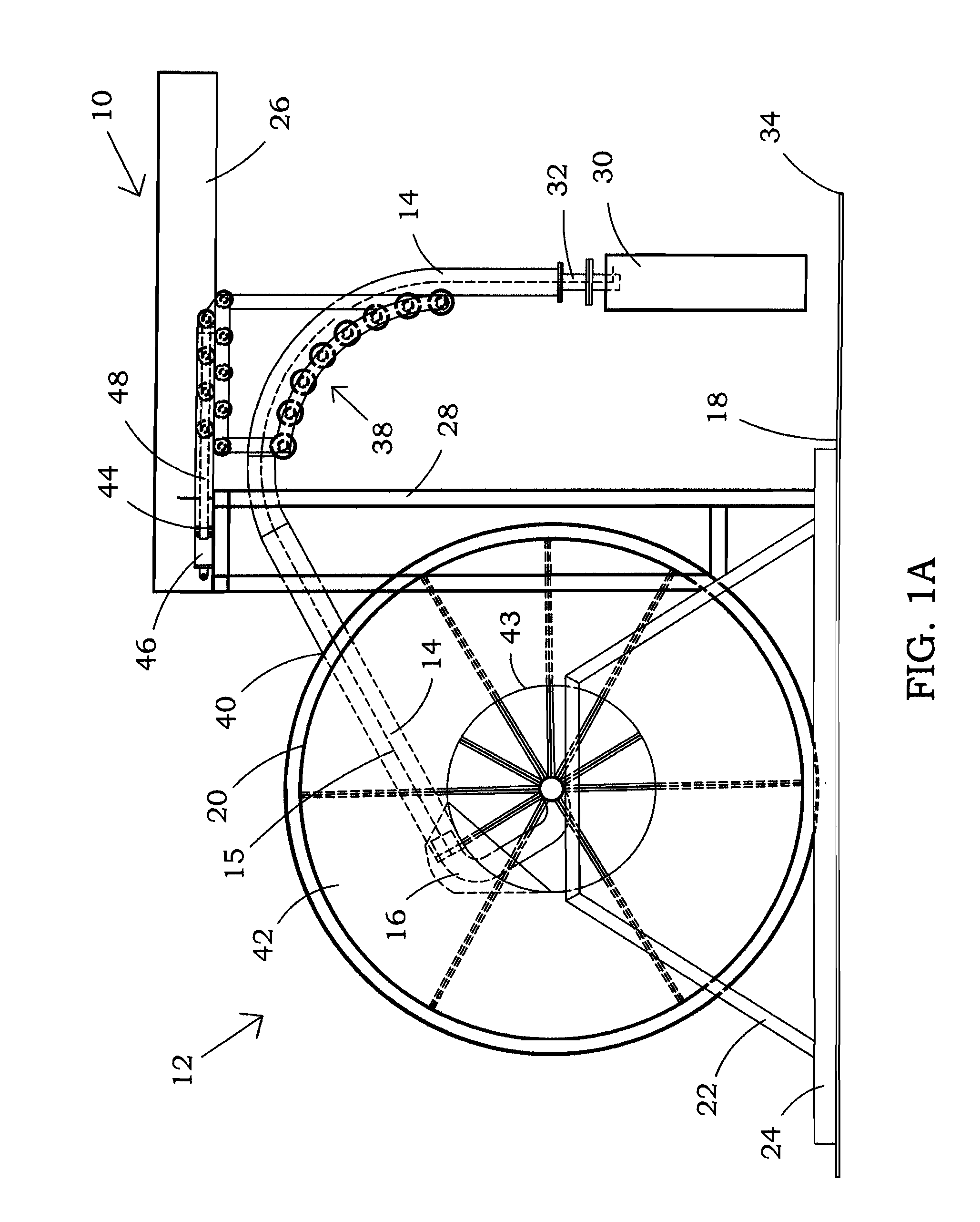
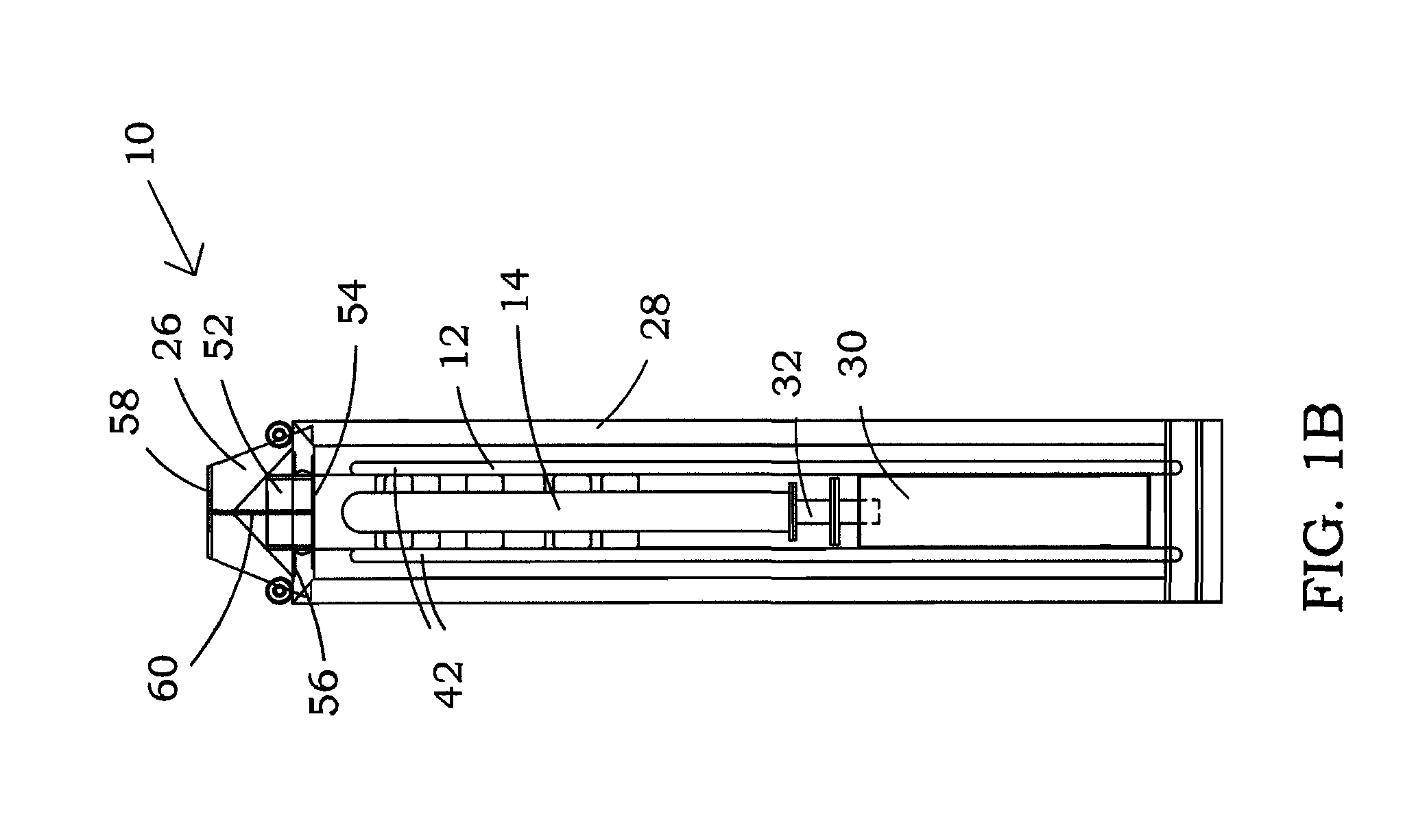
Referring now to the drawings and, more particularly, to FIGS. 1A and 1B, there is shown pump deployment system 10 in accord with one possible embodiment of the present invention.

The preferred embodiment of deployment system 10 of the present invention may be utilized on an offshore rig, which as used herein, may comprise any offshore vessel, rig, or the like, of which there are many kinds, commonly used in drilling, production, maintenance, and repair for offshore oil and gas wells.

Deployment system 10 is utilized in conjunction with a hose reel such as hose reel 12, which may be utilized to reel in and reel out hose 14 for inserting and removing a submersible pump into the water.

Hose 14 may preferably comprise heavy duty collapsible or non-collapsible hose. In one possible embodiment, hose 14 may comprise a rather large diameter in the range of about ten to eleven inches although hose 14 may be any desired diameter suitable for the desired flow rates, e.g., six to twenty inches, a...


PUM


Abstract

A deployment system is utilized to deploy an overboard pump over the side of an offshore rig or vessel. A reel of hose with an overboard pump is securable to an end of the reel of hose. A bend restrictor supports the hose as the hose bends downwardly for deployment in water. The bend restrictor is mounted for movement with respect to the reel whereby the bend restrictor is movable away from the reel, preferably along a fixed and predetermined path, to a deployment position to permit the overboard pump and the hose to be deployed into the water over the side of the offshore rig. The bend restrictor is also movable to a non-deployed position such that the hose guide is above the rig floor where the pump may be serviced.

Description

BACKGROUND OF THE INVENTION1. Field of the InventionThe present invention relates generally to overboard pumps that are deployed over the side of an offshore rig or vessel and, more particularly, to a deployment mechanism for use with a hose reel system comprising a movable bend restrictor for deploying and retrieving the overboard pump.2. Description of the Prior ArtHose reel systems designed to raise and lower electric motor driven submersible seawater pumps are well known and may be used for purposes such as supplying the offshore rig ballast water, raw sea water for rig use, such as engine cooling or fire water.Prior art hose reel systems of this type can require significant modification to the side and upper deck of the rig to provide a service deck and a scaffold with an opening for lowering the pump and for maintenance on the pump when the pump is raised to the side of the offshore vessel as well as mounting the reel system above the service deck. The scaffolding may typicall...

Claims


Application Information

Patent Timeline
IPC IPC(8): F04B53/00
CPCB63B17/00B65H75/4402F16L3/012F04D29/605F04D29/426
Inventor DRAPER, RICHARDRODRIGUEZ, LUIS MARIO
Owner S & N PUMP
Learn More