
Three-dimensional application program framework structure and a method for implementing an application program based on the same, and an automatic testing system based on a three-dimensional application software framework and a method therefor

a three-dimensional application and application software technology, applied in the field of three-dimensional application programs, can solve the problems of difficult use, difficult not only to develop, but also to maintain, the currently commercialized 3d application program in personal homes, research institutes, and small to medium-sized businesses, and achieve the effect of enabling the maintenance and stable execution of an application program

Inactive Publication Date: 2011-05-26
CODESE
View PDF14 Cites 87 Cited by
  • Summary
  • Abstract
  • Description
  • Claims
  • Application Information

AI Technical Summary

Benefits of technology

"The present invention provides a 3D application program framework structure and an automated test system for testing 3D application software. The framework structure includes a modeling component, a rendering component, a display component, a user extension component, and a framework system for connecting a user main module, modeling function components, and user-extensible components. The automated test system records user operations and automatically generates test cases based on relevant test cases recorded in a database, and executes automated tests on the 3D application software based on the test cases. The system also includes an automated test controller for controlling the execution of the automated tests and providing results to the user. The technical effects of the invention include facilitating the development of 3D application software and ensuring reliable and efficient testing of the software."

Problems solved by technology

However, 3D application program framework products provided in the related art provide just a basic Graphical User Interface (GUI) library, and they are expensive.
As such, it is difficult to use currently commercialized 3D application programs in personal homes, research institutes, and small to mid-sized businesses due to reasons of cost and functionality.
In an unsuccessful attempt to solve aforesaid problems, framework products have been developed, but they are difficult to use, such that it is difficult not only to develop, but also to maintain, the conventional 3D modeling application programs.
It is difficult to predict program reliability for these programs.
In this case, the conventional automated white-box test technology can be problematic.
Because a test case is generated based on source code, it is impossible to generate reliable test cases for a user's model selection operation having an infinite number of cases.
Further, the conventional automated white-box test technology is problematic in that functions must be called and variables must be adjusted at the time of replaying a test case.
Further, the conventional automated white-box test technology is problematic because it requires that a test case be generated by the analysis of source code, making it is impossible to generate a view manipulation test case and a selection test case.
This is because function-based input / output data must be stored and large-capacity model data requires an excessively large amount of memory, thereby making it impossible to use large-capacity model data.
However, this can be problematic.
For example, when user preferences such as the speed of screen manipulation (for example, rotation, magnification / reduction, and movement) and the sensitivity (range) and method of model selection, which directly influence the results of model selection, are changed after test cases are generated, identical operation results cannot be obtained, thus making it impossible to perform the test of functions of relevant application software.
That is, the conventional automated black-box test technology for recording a GUI event by a user and generating a test case can be problematic.
Further, the conventional automated black-box test technology is also problematic because it enables only a process test, which records a user's manipulation and generates and replays a test case, and a performance test, and the comparison of the results of the test is performed only by comparison between screen images.
It is impossible to compare data which is not displayed on the screen, and, in the case of model data having complicated and various components, it is difficult to analyze and treat ineffective resultant errors of modeling only by performing comparison between images.

Method used


Image

  • Three-dimensional application program framework structure and a method for implementing an application program based on the same, and an automatic testing system based on a three-dimensional application software framework and a method therefor
  • Three-dimensional application program framework structure and a method for implementing an application program based on the same, and an automatic testing system based on a three-dimensional application software framework and a method therefor
  • Three-dimensional application program framework structure and a method for implementing an application program based on the same, and an automatic testing system based on a three-dimensional application software framework and a method therefor

Examples


Embodiment Construction

[0045]Hereinafter, embodiments of a three-dimensional (3D) application program framework structure according to the present invention are described in detail with reference to the attached drawings.

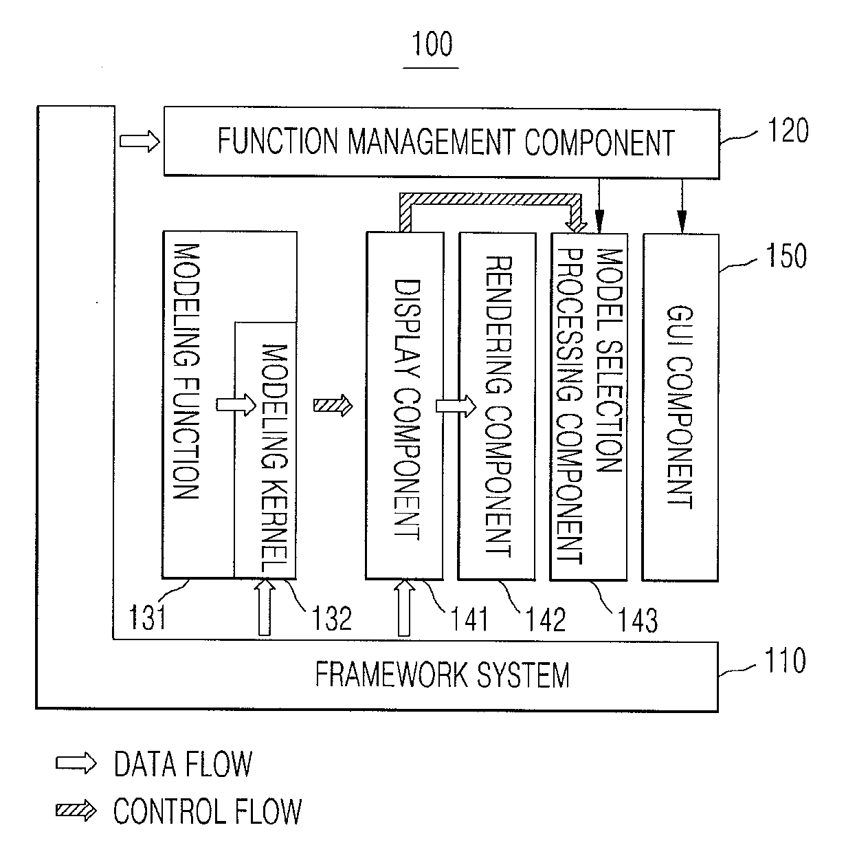
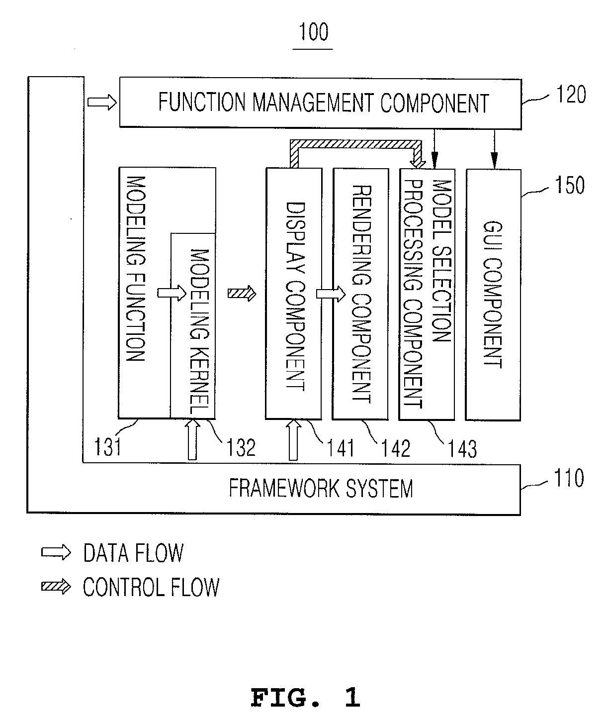
[0046]FIG. 1 is a diagram showing a basic framework structure according to an embodiment of the present invention. As shown in the drawing, the basic framework structure includes a modeling function component 131 including a 3D modeling utility and performing a modeling operation, a modeling kernel 132 for managing a plurality of pieces of 3D model data and applying the results of the modeling operation to relevant model data, a rendering component 142 for supporting a rendering tool such as openGL or DirectX, a display component 141 for supporting various types of model displaying and viewing (e.g., movement, rotation, magnification, and the like) based on the model data of the modeling kernel 132, and transmitting screen display data to the rendering component 142, a model selection pro...


PUM


Abstract

A three-dimensional application program framework structure; a method for implementing an application program based on the same; and an automatic testing system based on a three-dimensional application software framework and a method therefor. The three-dimensional application program framework structure provides a framework comprising functions and management of the environment of the system and events to be implemented by the user (developer), and the developer can easily expand the graphic user interface (GUI) and an actual modeling function as required, and user model. In addition, by using an automatic test system based on the framework, it is possible to record the function-execution history of the user and to automatically generate a test case, and to thereby test the functioning of the application software through the use of the test case regardless of changes in the source code and the GUI.

Description

CROSS-REFERENCE TO RELATED APPLICATIONS[0001]The present application is a national stage application under 35 U.S.C. §371 of International Application No. PCT / KR09 / 001031 with an international filing date of Mar. 3, 2009, and claims priority to KR10-2008-0019855, filed Mar. 4, 2008, and KR10-2008-0045885, filed May 19, 2008.BACKGROUND OF THE INVENTION[0002]1. Field of the Invention[0003]The present invention relates, in general, to three-dimensional application programs, and, more particularly, to technology for constructing a three-dimensional application program framework, a method of implementing an application program based on the framework, and automated test technology based on a three-dimensional application software framework.[0004]2. Discussion of Background Information[0005]Currently, technology supporting three-dimensional (3D) images and the modeling of 3D images has been presented, and the development of technology commercializing electronic home appliances and other el...

Claims


Application Information

Patent Timeline
Patent Type & Authority Applications(United States)
IPC IPC(8): G06F19/00G06F3/048G06T17/05
CPCG06T19/00G06F11/3684G06F11/3664
Inventor JUNG, BYUNG SOO
Owner CODESE
Learn More