Hinge and door unit

a technology for hinges and doors, applied in the field of hinges, to achieve the effect of improving the workability of mounting, reducing the number of mounting bolts, and easy and fine adjustment of a sta

Inactive Publication Date: 2011-06-02
CATEPILLAR SARL
View PDF20 Cites 16 Cited by
  • Summary
  • Abstract
  • Description
  • Claims
  • Application Information

AI Technical Summary

Benefits of technology

[0029]In another example, a plurality of second hinge plates are supported pivotally with a plurality of shaft members arranged on the same straight line so as to be capable of opening and closing with respect to the long first hinge plate, thereby integrating two hinges into one hinge. No reciprocal adjustment is needed between these two hinges, thus making it possible to easily and finely adjust a state where a door is mounted. The number of mounting bolts can also be decreased. Thus, it is possible to improve the mounting workability by using the hinge and also easily and finely adjust a state where the door is mounted. Further, since the long first hinge plate acts as a plate for integrating a plurality of hinges, it is not necessary to weld a plate between a plurality of hinges for integrating a plurality of hinges. Thus, unlike welded hinges, it is possible to omit a welding process and also improve the rigidity of the hinge.
[0030]Further more, the foamed material can be filled between the outer panel and the inner panel, thereby attaining a reduction in weight of the door panel main body and improvement of the vibration absorbing performance. Thus, it is possible to reduce loads acting on the hinges and also improve the durability of the hinges.

Problems solved by technology

However, this movement is positioning work accompanied by attachment and detachment of the stay 19s, which is troublesome and may be omitted in a work field.

Method used


Image

  • Hinge and door unit
  • Hinge and door unit
  • Hinge and door unit

Examples


Embodiment Construction

[0065]Hereinafter, the present invention will be described in detail by referring to an example illustrated in FIGS. 1 to 11, another example illustrated in FIGS. 12 to 16, a further example illustrated in FIG. 17, an additional example illustrated in FIGS. 18 to 28, the next example illustrated in FIG. 29, and an example illustrated in FIG. 30.

[0066]First, description will be made for the example illustrated in FIGS. 1 to 11.

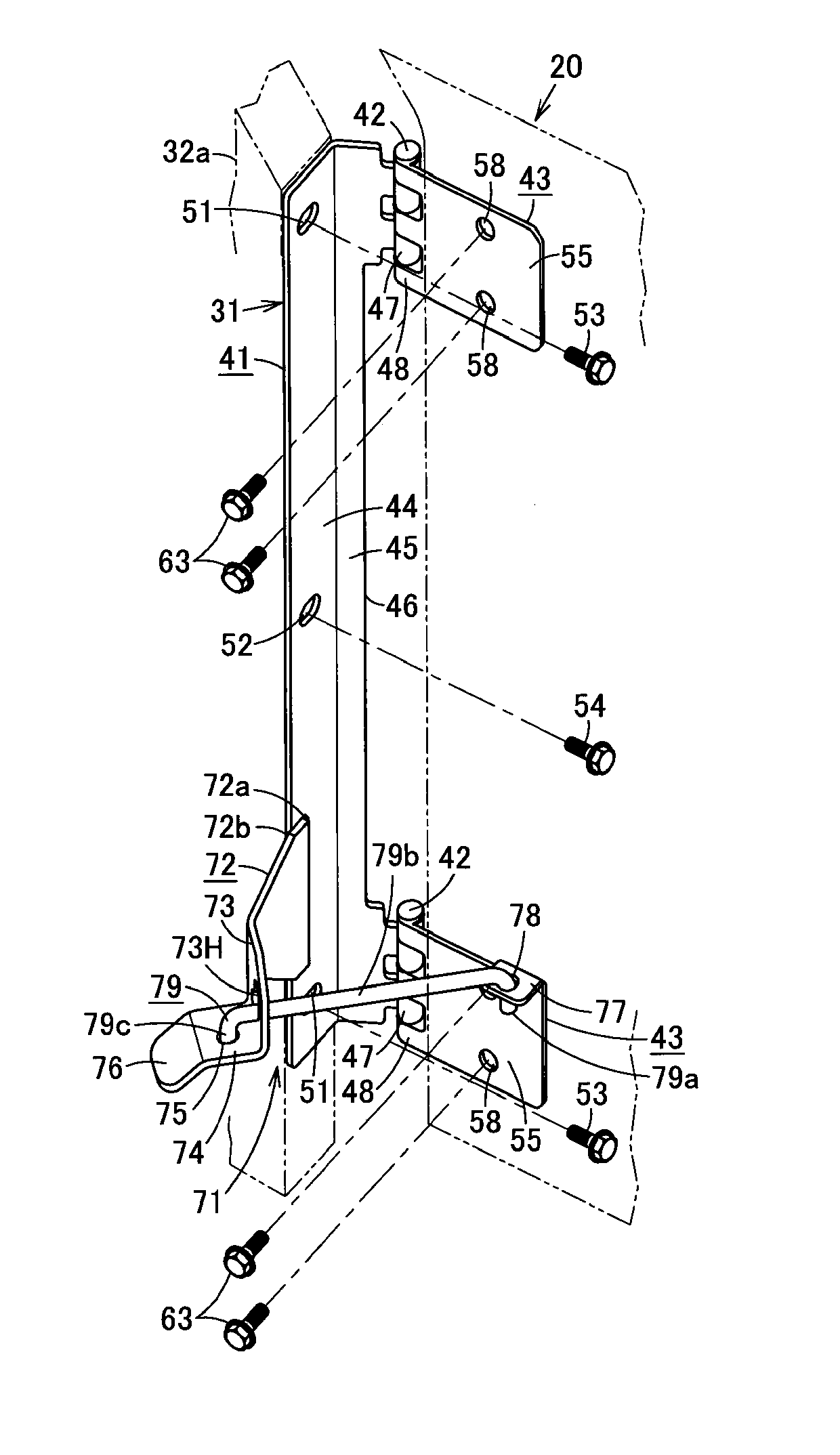
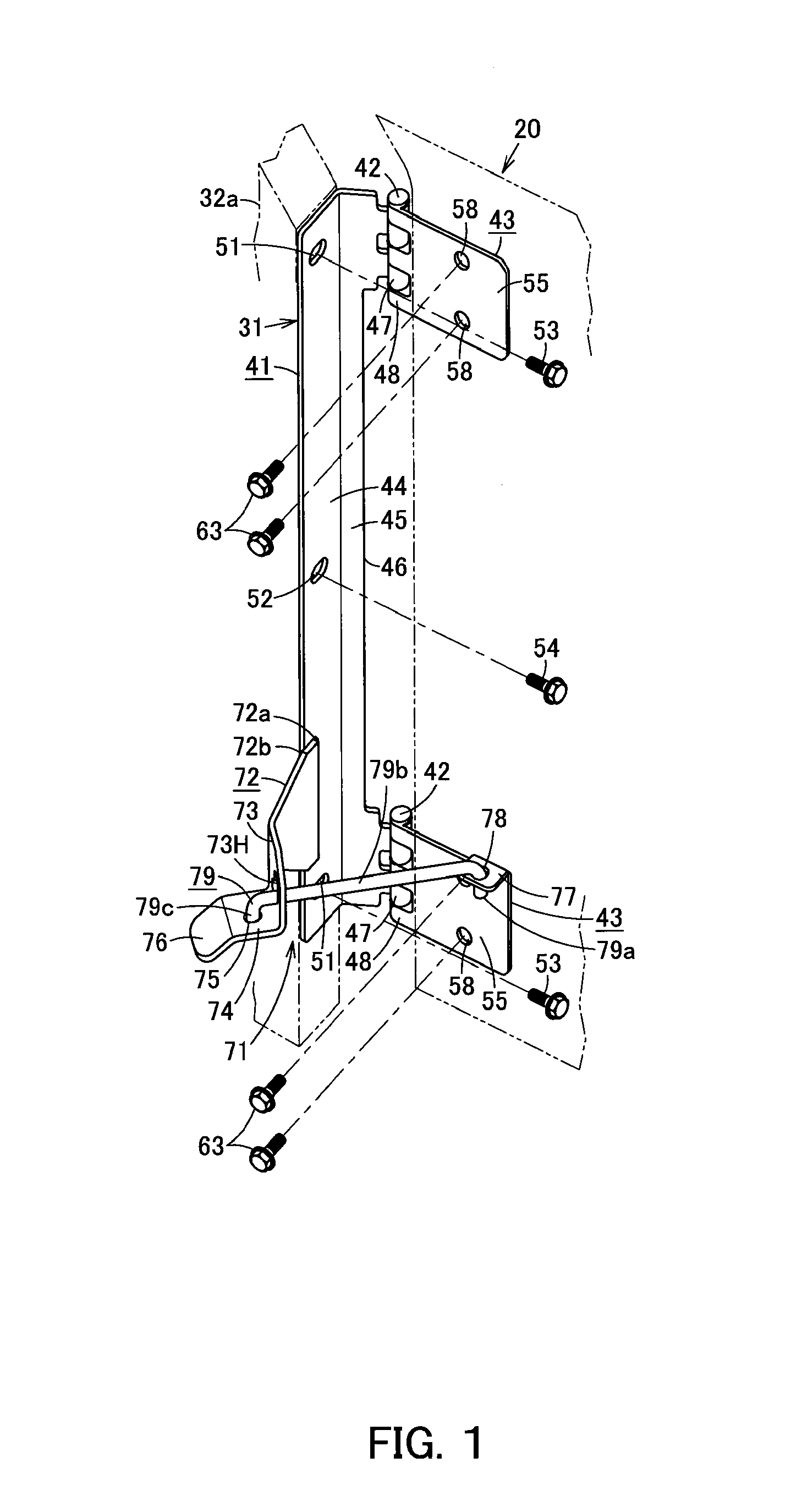
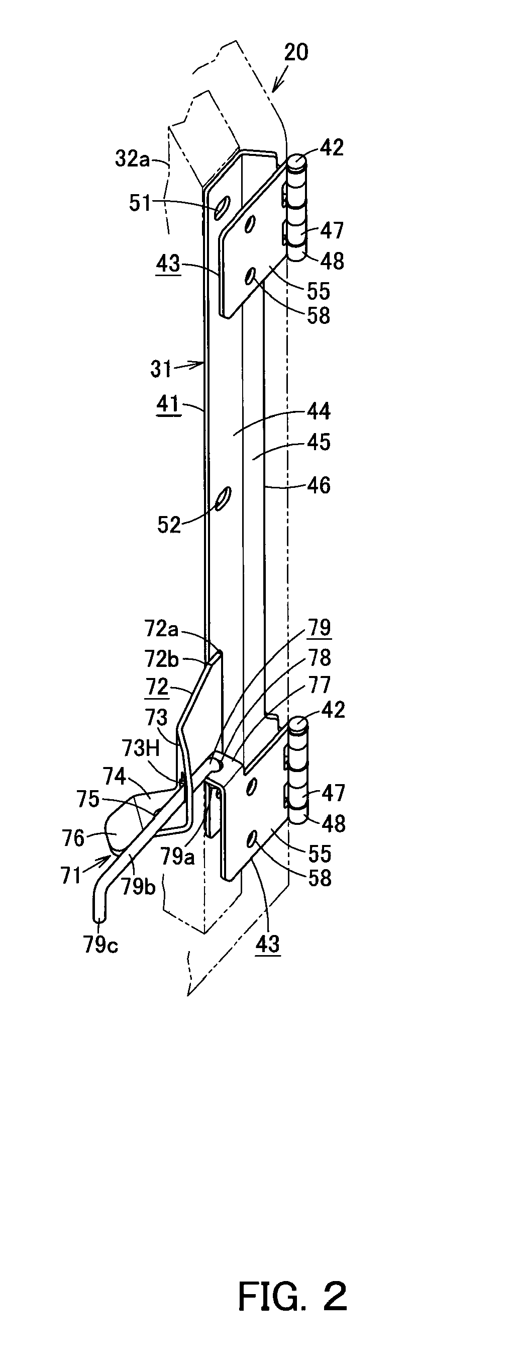
[0067]FIG. 7 illustrates a hydraulic excavator 10, which is a work machine. The hydraulic exactor 10 includes a lower structure 11, an upper structure 12, a cab 13, work equipment 14, and a power system 15 that includes an engine. The cab 13, the work equipment 14, and the power system 15 are mounted on the upper structure 12, which is rotatably mounted on the lower structure 11. The power system 15 is covered by a top cover 16, side doors 17 and others.

[0068]As illustrated in FIG. 8, one side of a door panel main body 20 of the side door 17 is mounted to a fra...


PUM


Abstract

A second hinge plate supported pivotally on a first hinge plate using a shaft member so as to open and close. In the second hinge plate, a bracket is molded integrally at the upper edge of the end opposite the shaft member. A vertical shaft of a hold-stay rod is loosely fitted into a shaft hole of the bracket so as to move rotationally and slide in a vertical direction. A horizontal shaft of the hold-stay rod is inserted into a guide hole of a guide plate welded to the first hinge plate and slidable, and a stopper is folded and formed at the leading end of the hold-stay rod. The stopper is inserted into an engaging hole by movement from a guide to a receiving plate due to the opening movement of the second hinge plate and can be taken out from the engaging hole by a pushing-up operation.

Description

CROSS REFERENCE TO PRIOR APPLICATIONS[0001]This application is a U.S. National Phase application under 35 U.S.C. §371 of International Application No. PCT / JP2009 / 059685, filed on May 27, 2009 and claims benefit of priority to Japanese Patent Application No. 2008-224582, filed on Sep. 2, 2008 and Japanese Patent Application No. 2009-002039, filed on Jan. 7, 2009. The International Application was published in Japanese on Mar. 11, 2010 as WO 2010 / 026806 A1 under PCT Article 21(2). All of these applications are herein incorporated by reference.TECHNICAL FIELD[0002]The present invention relates to a hinge for mounting a door panel main body to a frame and a door unit which is capable of being opened and closed by the hinge.BACKGROUND OF THE INVENTION[0003]FIG. 31 illustrates a hydraulic excavator 10, which is a work machine. The hydraulic exactor 10 includes a lower structure 11, an upper structure 12, a cab 13, work equipment 14 and a power system 15 that includes an engine. The cab 13...

Claims


Application Information

Patent Timeline
Patent Type & Authority Applications(United States)
IPC IPC(8): E05D11/06E06B3/36
CPCE02F9/00E02F9/0891E05C17/14Y10T16/551E05D11/06E05Y2900/518E05Y2900/531E05C17/22
Inventor UTO, RYOJIYOKOGAWA, KEITAROGOTO, TAKAHIROTAKEUCHI, SHIGEMI
Owner CATEPILLAR SARL
Why Eureka
Try Eureka