Force limiting device and method

a technology of force limit and limit device, applied in the direction of mechanical control device, process and machine control, instruments, etc., can solve the problem of unoptimized method, achieve the effect of optimizing robot design, improving compliance, and deteriorating performan

Active Publication Date: 2011-06-02
GM GLOBAL TECH OPERATIONS LLC +1
View PDF8 Cites 56 Cited by
  • Summary
  • Abstract
  • Description
  • Claims
  • Application Information

AI Technical Summary

Benefits of technology

[0018]As noted previously, collisions in which a contactable object is clamped to a wall or against another fixed object by a robot can be most severe. The force limiting mechanism described herein effectively reduces the maximum clamping force that the robot can apply in quasi-static condition to a force level determined by the limit torque levels set as limits for the torque limiters incorporated in the force limiting device. As the velocity of the robot system increases beyond a quasi-static, or very low velocity condition, compliance is improved because the inertia impacting the contactable object against the wall in a clamping condition is reduced. Because the force limiting mechanism is unable to store elastic potential energy, the robot will not continue to push on the contacted object after the collision has taken place and the force limiting device has been activated. This is an advantage since it will help the movement of the robot away from the contacted body after the collision.
[0019]As discussed previously, some robots incorporate a flexible flange with breakaway function to limit the moment, not the force, transmitted by the manipulator to the end-e

Problems solved by technology

However, this method is not optimized.
The threshold will also depend on the contact location and on the force orienta

Method used


Image

  • Force limiting device and method
  • Force limiting device and method
  • Force limiting device and method

Examples


Embodiment Construction

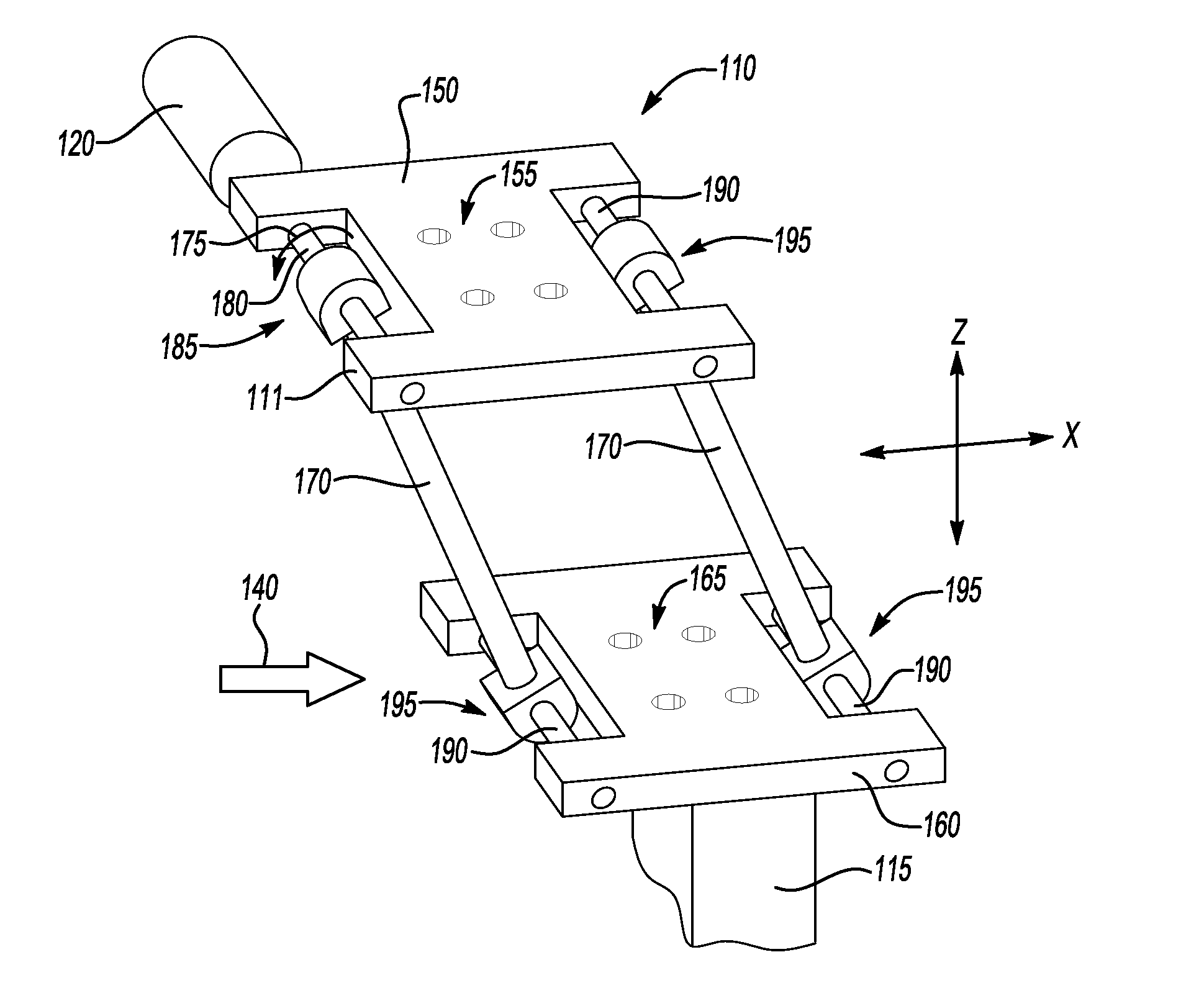
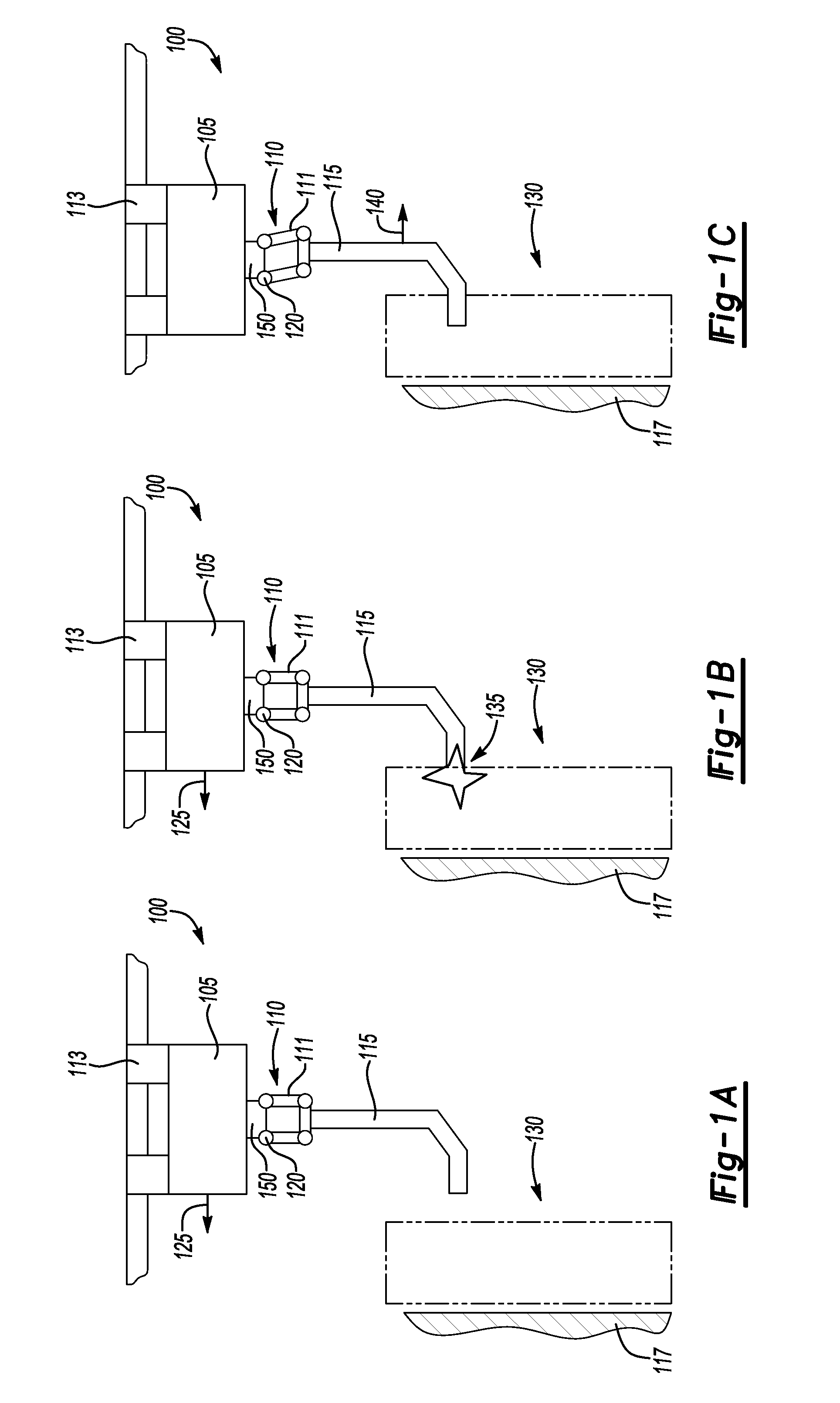
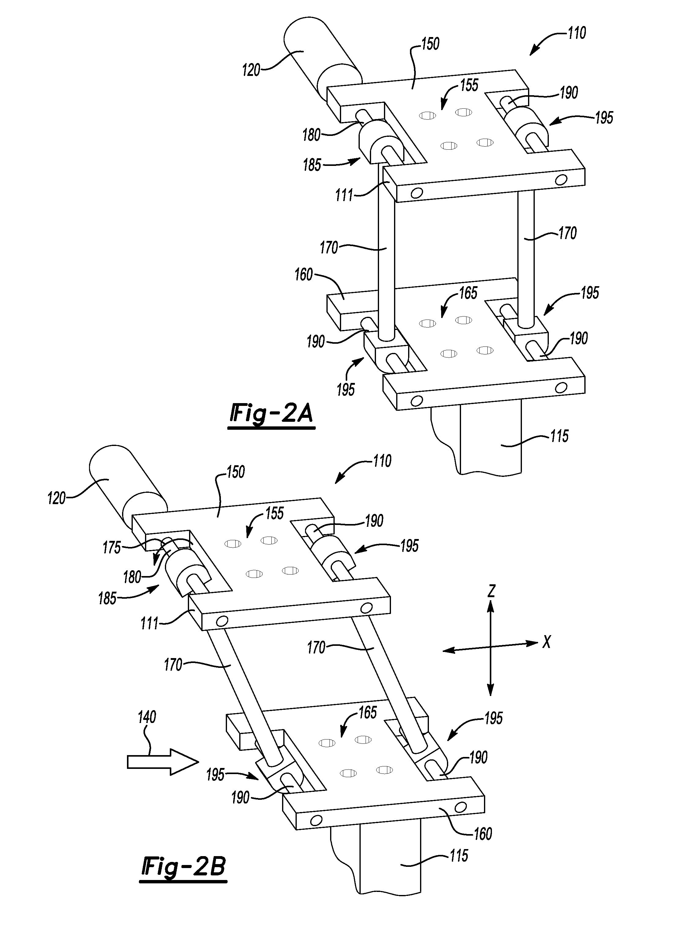
[0038]Provided herein is a force limiting device to increase the compliance level of suspended robots, as related to physical object-robot interfaces. The force limiting device described herein is a parallelogram mechanism with torque limiters which provide, during non-collision operation, a rigid connection between the robot and its end-effector. If an excessive force in a direction corresponding to the degrees of freedom (DOFs) for which the force limiting device is configured is applied during a collision, the force limiting mechanism is activated and the end-effector becomes compliant, e.g., is free to move relative to the robot and typically opposite to the direction of the collision. Brakes or like functioning devices are applied to stop further motion of the robot in the direction of contact when the force limiting device is triggered or activated. The inertia of the moving robot located kinematically upstream of the force limiting device is thus removed from the collision, a...


PUM


Abstract

The present invention relates to a method and apparatus for limiting the contact force between a moving device and another object, using a parallel mechanism and torque limiters where the threshold force to activate the force limiting mechanism is not related to the configuration of the moving device or the location of the contact force relative to the activation point of the force limiting mechanism, and where the mechanism may be configured for one, two or three degrees of freedom. A counterbalance mechanism is also provided to counteract gravity load when the force limiting mechanism is configured for three degrees of freedom and responsive to contact forces including a vertical element. In particular, the invention relates to a method and apparatus for limiting the contact force between a moving robotic device and a contactable object.

Description

TECHNICAL FIELD[0001]The present invention relates to a method and apparatus for limiting the force between a moving device and another object, using a parallel mechanism and torque limiters where the threshold force is not related to the device configuration, and in particular to limiting the collision or impact force between a moving robotic device and a contactable object.BACKGROUND OF THE INVENTION[0002]The use of industrial robots is well established in applications where the robots are in controlled environments where they are separated by fences or cages. A collision between a robot and a contacted object is a complex situation, where one of the most severe situations is when a collision with clamping occurs, entrapping the contacted object between the contacting portion of the robot and a static fixture, such as a wall. In this case, the severity of the collision may be indexed using the maximum contact force, which can then be used as a reference for unexpected collisions d...

Claims


Application Information

Patent Timeline
IPC IPC(8): B25J17/00B25J19/06B25J19/02
CPCB25J17/0208B25J9/0048B25J19/063B25J17/0266Y10T74/20305Y10T74/20329B25J17/00B25J19/0091Y10S901/28Y10S901/46
Inventor LAUZIER, NICOLASGOSSELIN, CLEMENTGAO, DALONGGRENIER, MARTINSTEVENSON, ROBIN
Owner GM GLOBAL TECH OPERATIONS LLC
Why Eureka
Try Eureka