Mounting device

a mounting device and mounting system technology, applied in the direction of photovoltaic modules, heat collector mounting/support, sustainable buildings, etc., can solve the problems of wasting a lot of material, not having a solid and fixed positioning mounting of photovoltaic modules, and more affected, and achieves a simple structured mounting system. , excellent lateral and longitudinal positioning

Inactive Publication Date: 2011-06-02
KERRYJ INVESTMENT
View PDF5 Cites 47 Cited by
  • Summary
  • Abstract
  • Description
  • Claims
  • Application Information

AI Technical Summary

Benefits of technology

[0007]It is an object of the invention to overcome or at least ameliorate one or more of the problems of the prior art by providing a simple structured mounting system, having excellent lateral and longitudinal location.
[0015]There is also provided a mounting rack structure for mounting a photovoltaic module including a substantially H cross sectional structure with a front wall and a back wall and a closed base wall and two different entrances forming two input spaces each providing a space to input one of the at least two clamps and wherein the two input spaces are mutually perpendicular to form a longitudinal input space and a lateral input space to allow for the substantially perpendicular orientation of the open entrances of the two input spaces to receive two of the at least two clamps in substantially perpendicular arrangement to each other and allow relative mounting of the photovoltaic module to the rack and the rack to a supporting structure.
[0026]Therefore, we can get the effect of lateral and longitudinal location by forming two stop blocks on the Input space in the side. It is much simpler than the current technique (American patent US2006 / 0156651), then save material. Otherwise, clamp of this utility model needn't to be incurved into “L”, so clamp of this model has better structure intensity when using material of same volume.

Problems solved by technology

However such a shape and size makes them more affected by wind, so the installation fixture must have strong location capacity and structure strength.
However there is substantial movement of the intricate arrangement and interconnection of L-shaped clamp and therefore not a solid and fixed positioning mounting of the photovoltaic modules.
Also the photovoltaic modules have large area and perimeter taking substantial fitting space, and the rail 1 needs to be a single length, and so wastes a lot of material and the costs rise correspondingly.

Method used


Image

  • Mounting device
  • Mounting device
  • Mounting device

Examples


Embodiment Construction

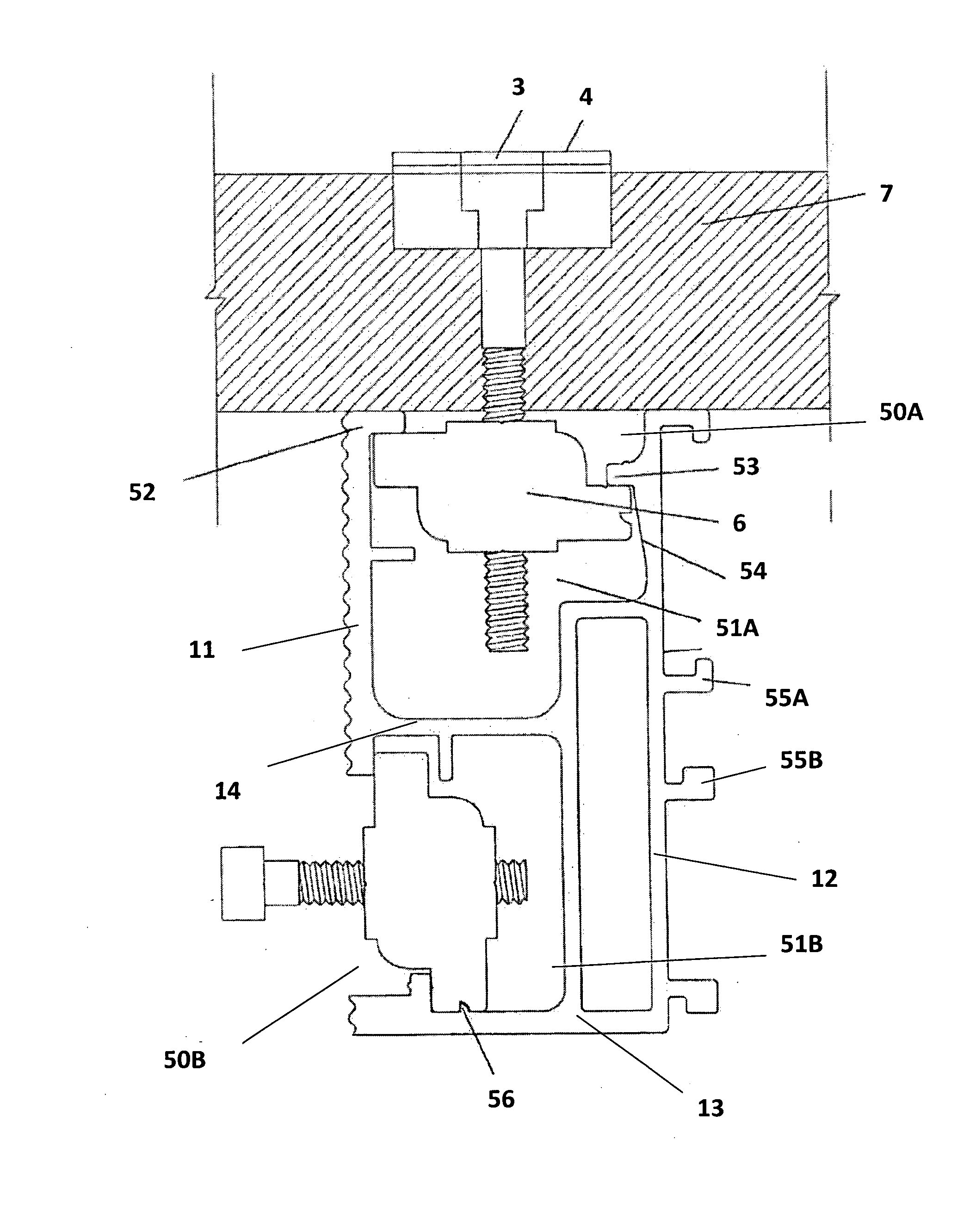
[0036]An embodiment of the invention is shown in FIGS. 3 to 8. FIGS. 3 and 4 are an example of photovoltaic modules mounting system using this invention and includes a mounting rack structure a rail 5 and two clamps 6 for holding a photovoltaic module 7 by a bolt 3 extending from a press plate 4 on an outer side of the module 7 to one of the clamps 6 mounted in an upper input space 51A in the rail 5.

[0037]The rail 5 is continuous elongated rail with primarily a substantially consistent H cross sectional structure with a front wall 11, a back wall 12 and a closed base wall 13 with a cross member 14 extending substantially across a middle section between the front wall towards the back wall to define two input spaces 51A and 51B. Entrances 50A and 50B are provided relatively for each of the two input spaces 51A and 51B each providing a space to input one of the at least two clamps 6.

[0038]As shown in FIG. 4, the Rail 5 has two input spaces 51A and 51B with different orientations, whic...


PUM


Abstract

A photovoltaic module mounting system having a rack structure, which includes a mounting rack structure having a rail (5) and two clamps (6) for holding a photovoltaic module (7) by a bolt (3) extending from a press plate (4) on an outer side of the module (7) to one of the clamps (6) mounted in an upper input space (51A) in the rail (5). Entrances (50A and 50B) are provided relatively for each of the two input spaces (51A and 51B) each providing a space to input one of the at least two clamps (6), which are mutual perpendicular. The longitudinal input space (51A) in the upper section of the substantially H shape rail is used to hold the clamp (6) to fix the photovoltaic module (7). The lateral input space (51B) is used to hold the clamp (6) to fix the rail (5) to the pre-location. It has an excellent function on lateral and longitudinal location. And the structure is simple, compact, efficient, adaptable and saves on material.

Description

TECHNICAL FIELD[0001]This patent relates to a mounting system, for mounting a photovoltaic module. It is particularly used for outdoor mounting installation of photovoltaic modules.BACKGROUND TECHNOLOGY[0002]Solar energy is applied in all kinds of fields and plays a wide role in people's daily life, particularly with the development of science and technology as well as the growth of people's environmental consciousness. Solar water heater, solar energy car, solar energy yacht and solar energy bicycle have been coming into more common use gradually, especially solar water heater which has already been used widely.[0003]Photovoltaic modules (PV modules) or “solar panels” are the core part of a solar generated electricity system. It undertakes the process of transforming solar radiant energy into electricity, which is then stored in a solar cell or battery or directly used in relevant work. Therefore photovoltaic modules (PV modules) or “solar panels” must be installed outdoors, such a...

Claims


Application Information

Patent Timeline
Patent Type & Authority Applications(United States)
IPC IPC(8): H01L31/042
CPCF24J2/5205F24J2/5258F24J2/526F24J2002/5215F24J2002/5226F24J2002/5281Y10T403/4677Y02E10/50Y02B10/12F24J2002/467H02S20/00H02S20/23Y02E10/47F24S25/33F24S25/636F24S25/65F24S2025/014F24S2025/018F24S2025/6007F24S2025/801F24S2025/807F16B2200/40Y02B10/10
Inventor HONG, XUWENWANG, XIAOMING
Owner KERRYJ INVESTMENT
Why Eureka
Try Eureka