Engine mount of aircraft and aircraft

a technology for aircraft and aircraft, applied in aircraft power plants, power plant construction, power plant types, etc., can solve problems such as increasing weight, and achieve the effect of improving maintainability and reducing the installation of reinforcing rods

Active Publication Date: 2011-06-02
MITSUBISHI AIRCRAFT
View PDF9 Cites 44 Cited by
  • Summary
  • Abstract
  • Description
  • Claims
  • Application Information

AI Technical Summary

Benefits of technology

[0010]The present invention is accomplished in view of such a technical problem, and has an object to provide an engine mount of an aircraft and the aircraft, which can reduce a size of an engine mount and can effectively use a space in an engine nacelle even in the engine with a high bypass ratio.
[0013]Further, the pylon side mount member can include a pair of plate-shaped main mount members provided to sandwich the pylon strut therebetween, and a reinforcing mount member which is sandwiched between the pair of the main mount members, and reinforces support strength of the main mount member in a direction to connect the pair of main mount members.
[0015]A reinforcing rod with one end connected to an upper end portion of the engine side mount member and the other end connected to a vicinity of a boundary portion of the engine core section and the fan section may be further provided. In this case, the height of the engine side mount member is suppressed to be low, and therefore, the reinforcing rod also can be installed to be low. Thereby, when devices are installed between the engine core section and the pylon strut, the reinforcing rod hardly interferes with maintenance of these devices, and maintainability can be improved.
[0017]According to the present invention, at least the rear engine mount is configured by the engine side mount member and the pylon side mount member. Thereby, the engine side mount member and the pylon side mount member can be made short respectively as compared with the case of using the rear engine mount made by integrating the engine side mount member and the pylon side mount member. Thereby, the moments of the forces which work on the engine side mount member and the pylon side mount member due to relative displacement of the engine and the wing can be made small. Accordingly, in the engine with a high bypass ratio, the engine mount can be made compact, and the space in the engine nacelle can be effectively used.
[0018]Further, while the support strength in the longitudinal direction and the vertical direction of the aircraft corresponding to the directions along the plate surface is mainly secured by a pair of plate-shaped main mount members which are provided to sandwich the pylon strut, support strength of the main mount member in the direction to connect a pair of main mount members, that is, the thickness direction of the plate is reinforced by the reinforcing mount member which is inserted between a pair of main mount members, whereby, support strength for the engine to every direction can be secured.
[0019]Further, the height of the engine side mount member is suppressed to be low, and therefore, the reinforcing rod can be installed to be low. Thereby, when the devices are installed between the engine core section and the pylon strut, the reinforcing rod hardly interferes with maintenance of these devices, and maintainability can be improved.

Problems solved by technology

As a result, in order to secure the strength of the rear engine mount 6, the rear engine mount 6 has to be made thick or the like, and this leads to an increase in weight.

Method used


Image

  • Engine mount of aircraft and aircraft
  • Engine mount of aircraft and aircraft
  • Engine mount of aircraft and aircraft

Examples


second embodiment

[0045]Next, a second embodiment of the engine mount of an aircraft according to the present invention will be described. In the engine mount of an aircraft which will be described as follows, the basic configuration is similar to that shown in the above-described first embodiment. Therefore, the difference will be mainly described in the following, and the components common to the above described first embodiment will be assigned with the same reference numerals and characters, and the description of them will be omitted.

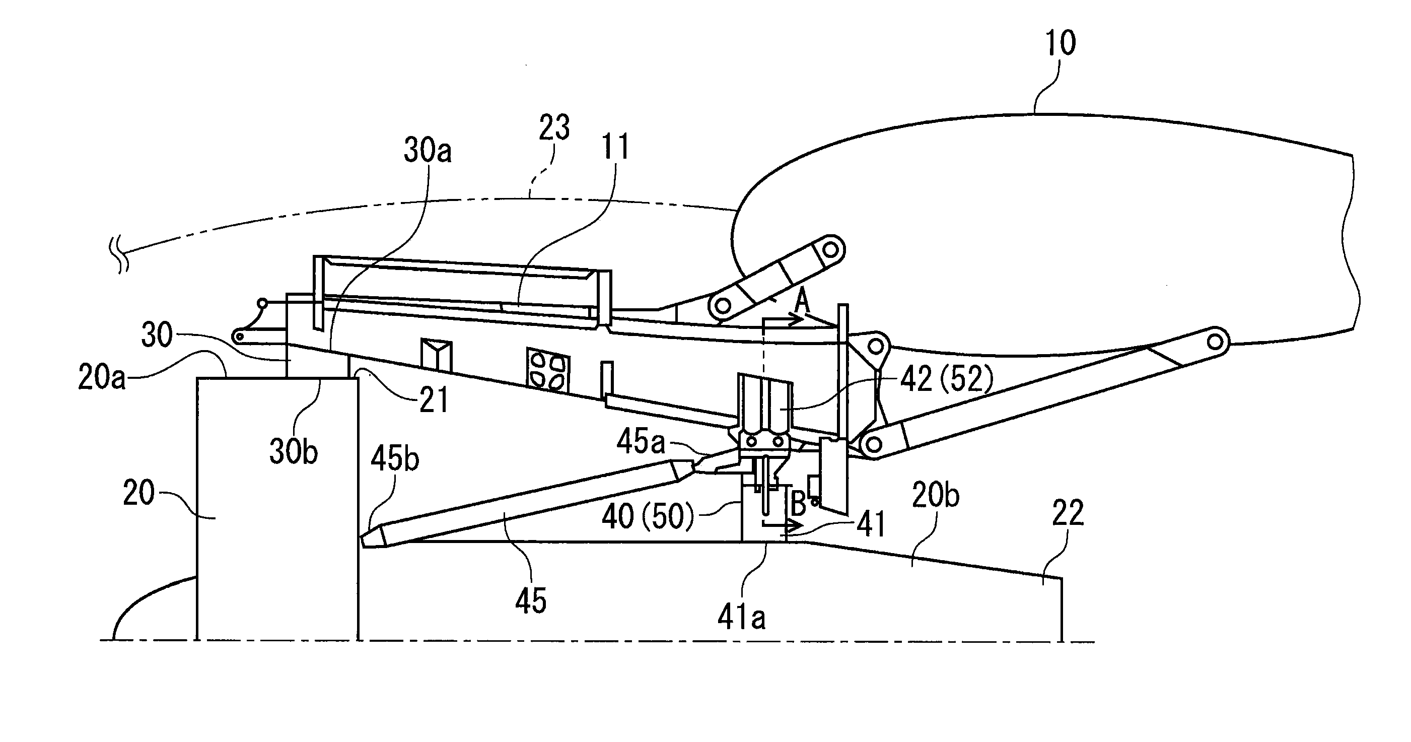
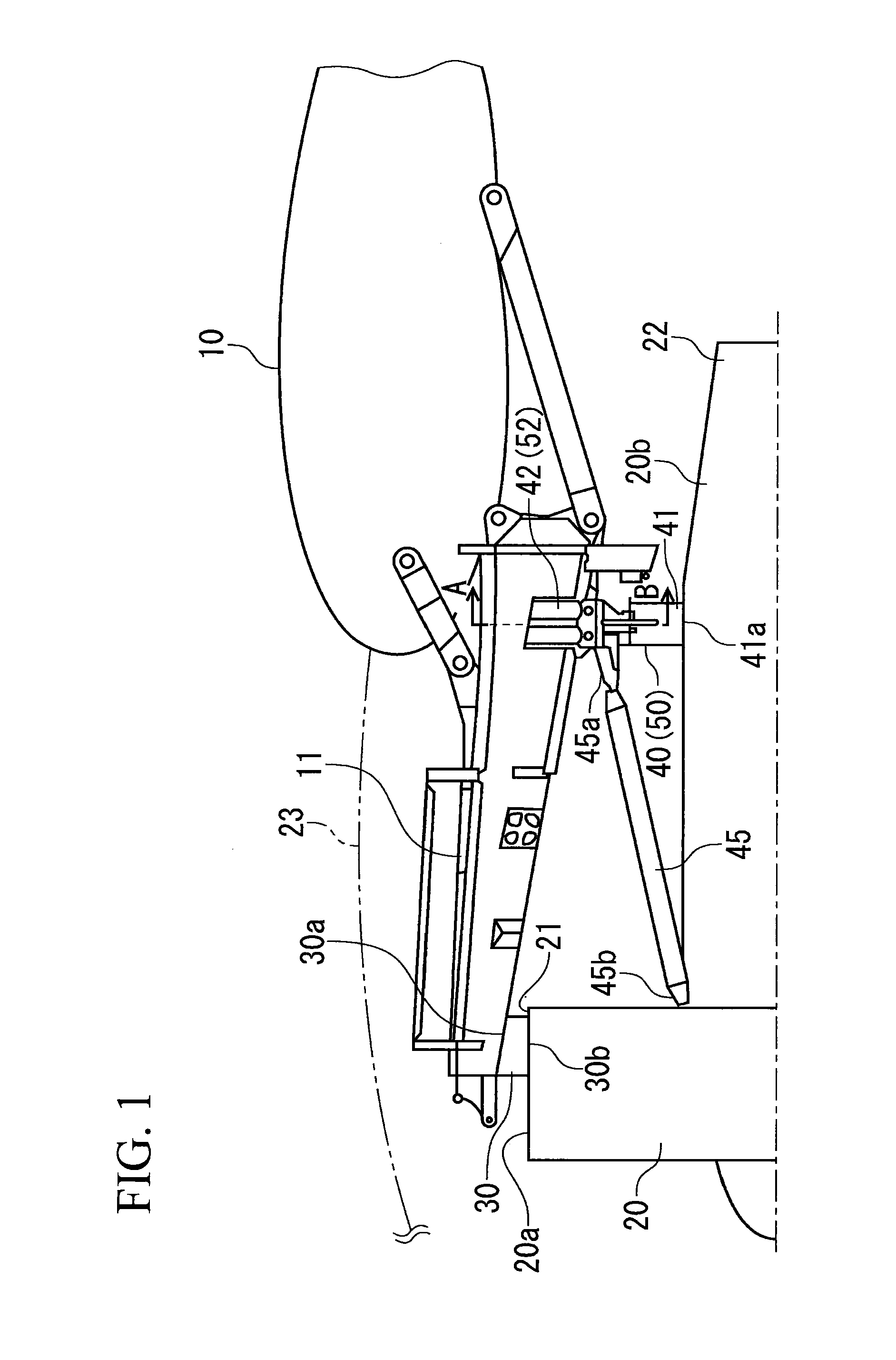
[0046]As shown in FIG. 1, the engine 20 has the fan section 20a mounted to the undersurface of the pylon strut 11 by the front engine mount 30, and has the engine core section 20b mounted to the undersurface of the pylon strut 11 by a rear engine mount 50.

[0047]The rear engine mount 50 comprises the engine side mount member 41 fixed to the engine 20 side, and a strut side mount member 52 fixed to the pylon strut 11 side.

[0048]As shown in FIGS. 3A and 3B, the strut s...


PUM


Abstract

An engine mount of an aircraft and an aircraft are provided, which can reduce a size of an engine mount and can effectively use a space in an engine nacelle even in an engine with a high bypass ratio. An engine core section 20b at a rear of an engine 20 is supported by a rear engine mount 40 comprising an engine side mount member 41 fixed to a side of the engine 20 and a strut side mount member 42 fixed to a side of a pylon strut 11. The rear engine mount 40 is divided into the engine side mount member 41 and the strut side mount member 42, and thereby, even in the engine 20 with a high bypass ratio in which an outside diameter of the fan section 20a and the outside diameter of the engine core section 20b significantly differ, the lengths in the vertical direction of the engine side mount member 41 and the strut side mount member 42 are suppressed.

Description

BACKGROUND OF THE INVENTION[0001]1. Field of the Invention[0002]The present invention relates to an engine mount of an aircraft including a turbofan type engine, and the aircraft.[0003]2. Description of the Related Art[0004]A turbofan type engine of an aircraft is mounted to a wing via a structural member called a pylon strut (see, for example, FIG. 13.4.3 of “Airframe structural design second edition” by Micheal C. Y. Niu, Hong Kong Conmilit Press LTD pp. 482 to 483).[0005]As shown in FIG. 4, a pylon strut 1 is provided at an undersurface of a wing 2 to extend toward a front in a flying direction. In an engine 4, a fan section 4a at the front is mounted to an undersurface of the pylon strut 1 by a front engine mount 5, and a core section 4b at the rear is mounted to the undersurface of the pylon strut 1 by a rear engine mount 6.[0006]Forces in various directions work between a side of the engine 4 and a side of the pylon strut 1. For example, by the thrust force of the engine 4, an...

Claims


Application Information

Patent Timeline
Patent Type & Authority Applications(United States)
IPC IPC(8): B64D27/26
CPCB64D27/18Y02T50/44B64D2027/264B64D27/26Y02T50/40
Inventor TAKEUCHI, AKIRA
Owner MITSUBISHI AIRCRAFT
Why Eureka
Try Eureka