

Magnetic gear
a magnetic gear and gearing technology, applied in the direction of synchonous clutches/brakes, dynamo-electric brake control, mechanical energy handling, etc., can solve the problems of poor torque transmission capability, poor reliability, and limited use of magnetic gearing, so as to reduce current
- Summary
- Abstract
- Description
- Claims
- Application Information
AI Technical Summary
Benefits of technology
Problems solved by technology
Method used
Image

Examples
first embodiment
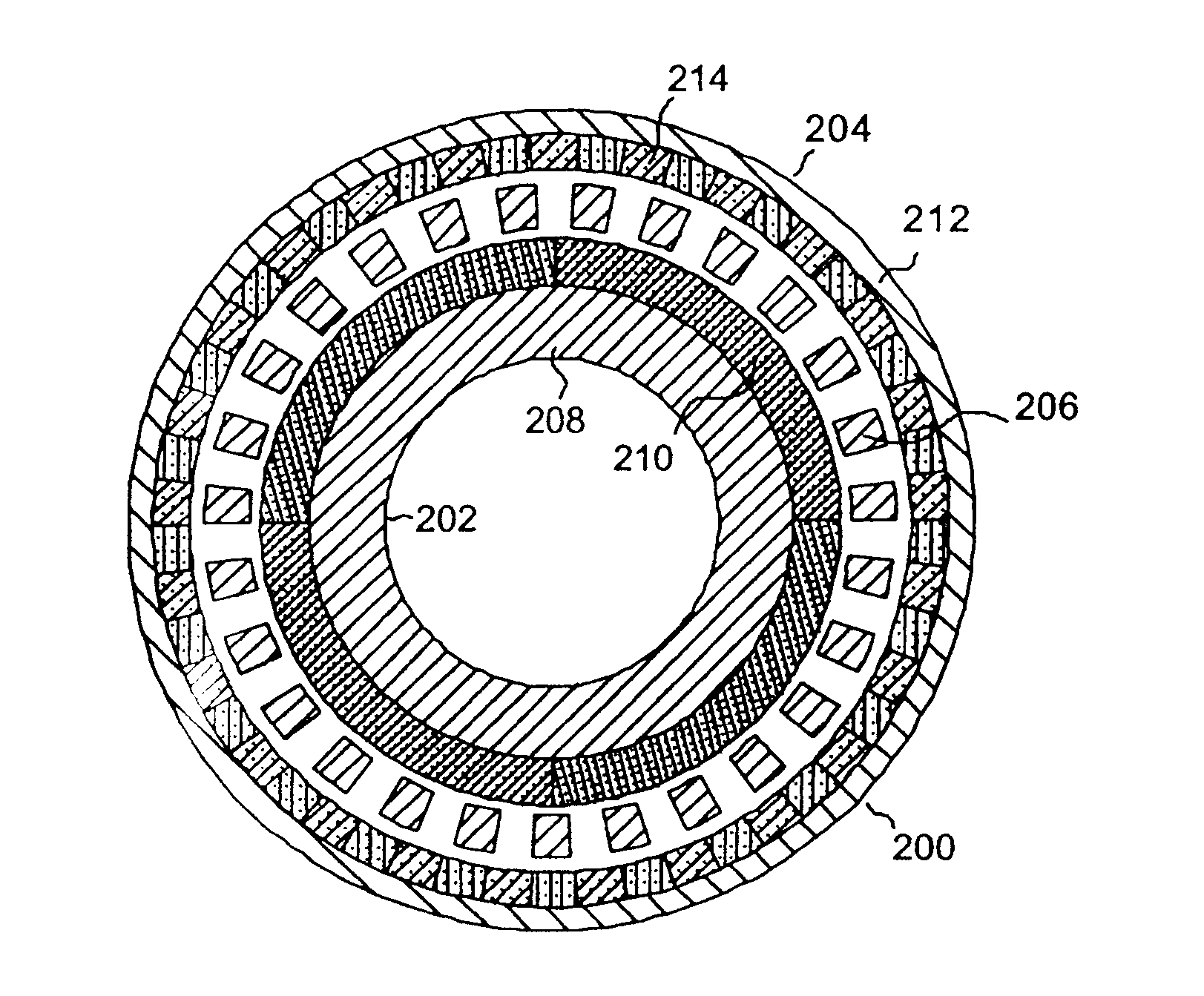
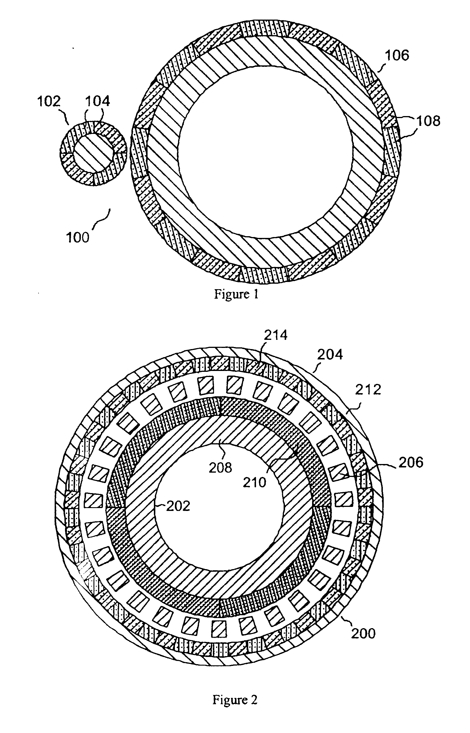
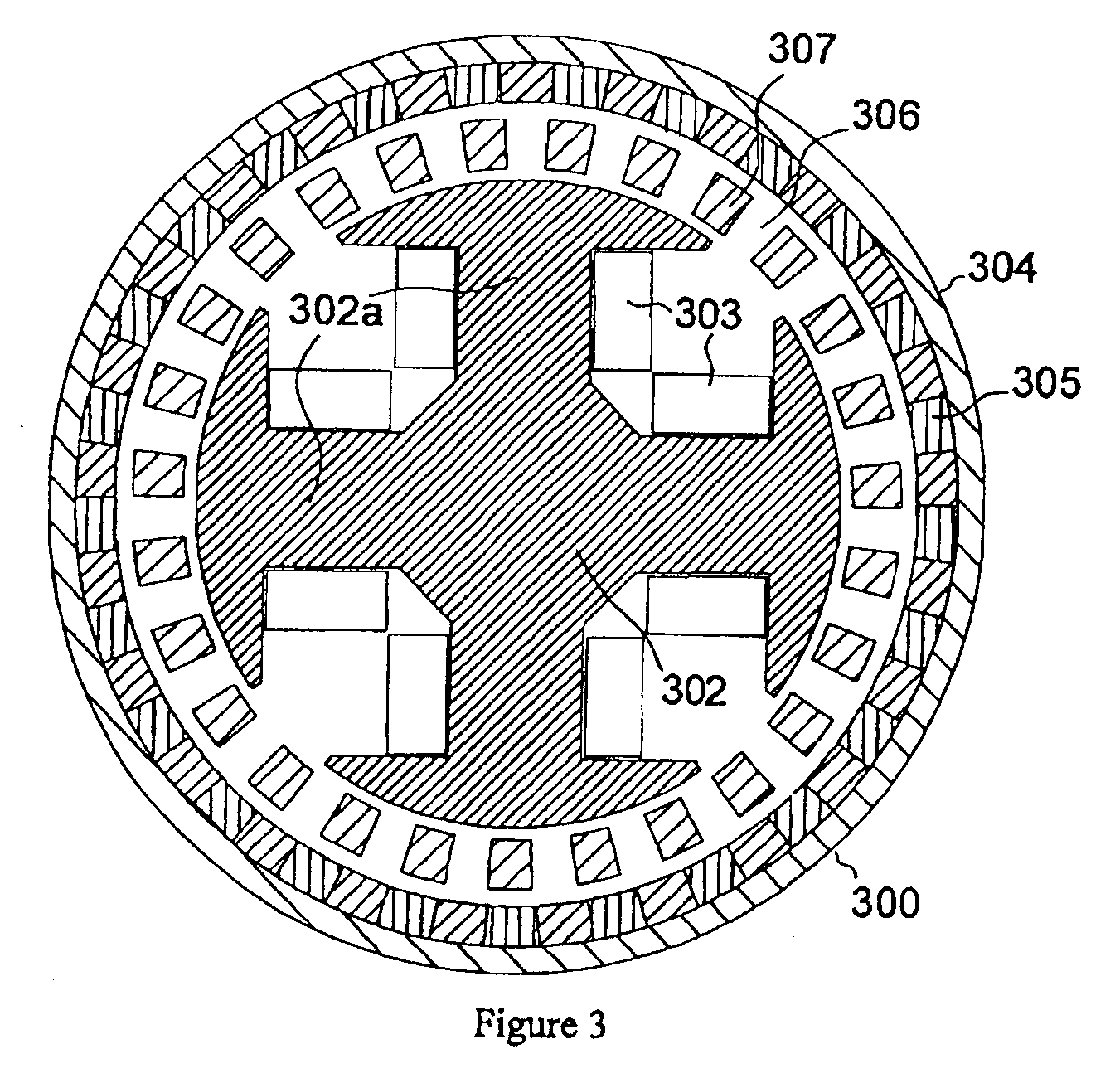
[0021]FIG. 3 shows a magnetic gear ;
[0022]FIG. 4 shows a graph of load-angle against torque for a prior art magnetic gear;
[0023]FIG. 5 illustrates a graph of load-angle against torque for a magnetic gear according to embodiments of the present invention;
[0024]FIG. 6 depicts a magnetic gear according to a further embodiment;
[0025]FIG. 7 shows another embodiment of a magnetic gear; and
[0026]FIG. 8 illustrates yet another embodiment of a magnetic gear;
[0027]FIG. 9 illustrates yet another embodiment of a magnetic gear;
[0028]FIG. 10 illustrates yet another embodiment of a magnetic gear; and
[0029]FIG. 11 illustrates yet another embodiment of a magnetic gear.
[0030]Detailed description of preferred embodiments FIG. 3 shows a magnetic gear 300 according to a first embodiment. The magnetic gear 300 comprises an inner rotor 302, an outer rotor 304 and a stator 306 interposing the inner 302 and outer 304 rotors. The inner 302 and outer 304 rotors are rotatable, as will be explained, and the sta...
embodiment 400
[0044]The second preferred embodiment 400 comprises an outer rotor 404 carrying a plurality of permanent magnets 405 and a stator 406 comprising a plurality of pole pieces 407 as in the first preferred embodiment.
[0045]The second embodiment 400 further comprises an inner rotor 402 carrying a plurality of windings 403 which form electromagnets. The windings 403 are arranged in open slots, or blind-apertures, distributed around the outer circumference or periphery of the inner rotor 402. The windings 403 are arranged in layers within the open slots. The windings which are shown in FIG. 6 are configured to result in a magnetic field which has 4 poles. The current in the windings 403 may be an AC or a DC current. When a DC current is applied to the windings 403, the magnetic field is stationary compared to the inner rotor 402, and hence moves at the same speed as the mechanical speed of the inner rotor 402 compared to an external reference frame. In case an AC current is applied to the ...
sixth embodiment
[0058]FIG. 10 illustrates the invention. An axial-field magnetic gear 800 is axisymmetric around axis 811 and comprises a low-speed rotor 806 which is connected with two discs 811a and 811b carrying a plurality of pole-pieces 807a and 807b. An inner rotor 802 carries a plurality of windings 803 forming electromagnets. The embodiment further comprises stators 804 to which two discs 809a and 809b are attached, which contain pluralities of permanent magnets 80Sa and 805b. Although the embodiment is described in relation to rotors 802 / 806 and a stator 804, it is not essential to the principle of the invention which component is configured to be stationary, and which component functions as the input rotor or output rotor.
[0059]The sixth embodiment 800 is shown to be symmetric around a symmetry plane which cuts through the centre of disc 802 and is perpendicular to the symmetry axis 811. The components which are symmetric to one another have been referred to in FIG. 10 with identical numb...
PUM
 Abstract
Description
Claims
Application Information