Forced discharge mechanism and safety switch device for storage battery

Inactive Publication Date: 2011-06-02
SHARP KK
View PDF5 Cites 717 Cited by
  • Summary
  • Abstract
  • Description
  • Claims
  • Application Information

AI Technical Summary

Benefits of technology

[0071]As described above, according to the forced discharge mechanism for a storage battery and the safety switch device according to the present invention, it is possible to improve safety when an abnormal condition such as getting wet occurs, without using an electrical control configuration.
[0072]Specifically, according to the forced discharge mechanism for a storage battery and the safety switch device according to the present invention, since the electric resistor is moved due to the buoyant force of liquid that has entered, conduction between the power transport paths can be established by the moved electric resistor upon ingress of liquid, which enables voluntary and automatic discharge of the storage battery. Thus, even if ingress of liquid (e.g., getting wet due to a flood etc.) occurs, the occurrence of an electric leakage or a short circuit due to liquid can be suppressed between the positive and negative electrode terminals of the storage battery, and consequently it is possible to suppr

Problems solved by technology

If liquid such as water or sea water enters into such storage batteries when an abnormal condition such as getting wet occurs, an electric leakage or a short circuit occurs between positive and negative electrode terminals of the storage batteries, which may cause a problem such as generation of heat.
Specifically, with regard to the environment where storage batteries are used, there are concerns about the influence on storage batteries of getting wet or the like, due to cars becoming submerged or being washed away as a result of roads becoming covered in water or flooded caused by the overflowing of rivers, or to houses becoming immersed in water, for instance, because of the recent abnormal weather or the like.
However, with the battery pack described in Patent Document 1, although power supply between the external power source and the storage battery can be interrupted by blowing the thermal fuse connected in series to the power transport path between the external power source and the storage battery with the means for detecting ing

Method used


Image

  • Forced discharge mechanism and safety switch device for storage battery
  • Forced discharge mechanism and safety switch device for storage battery
  • Forced discharge mechanism and safety switch device for storage battery

Examples


first embodiment

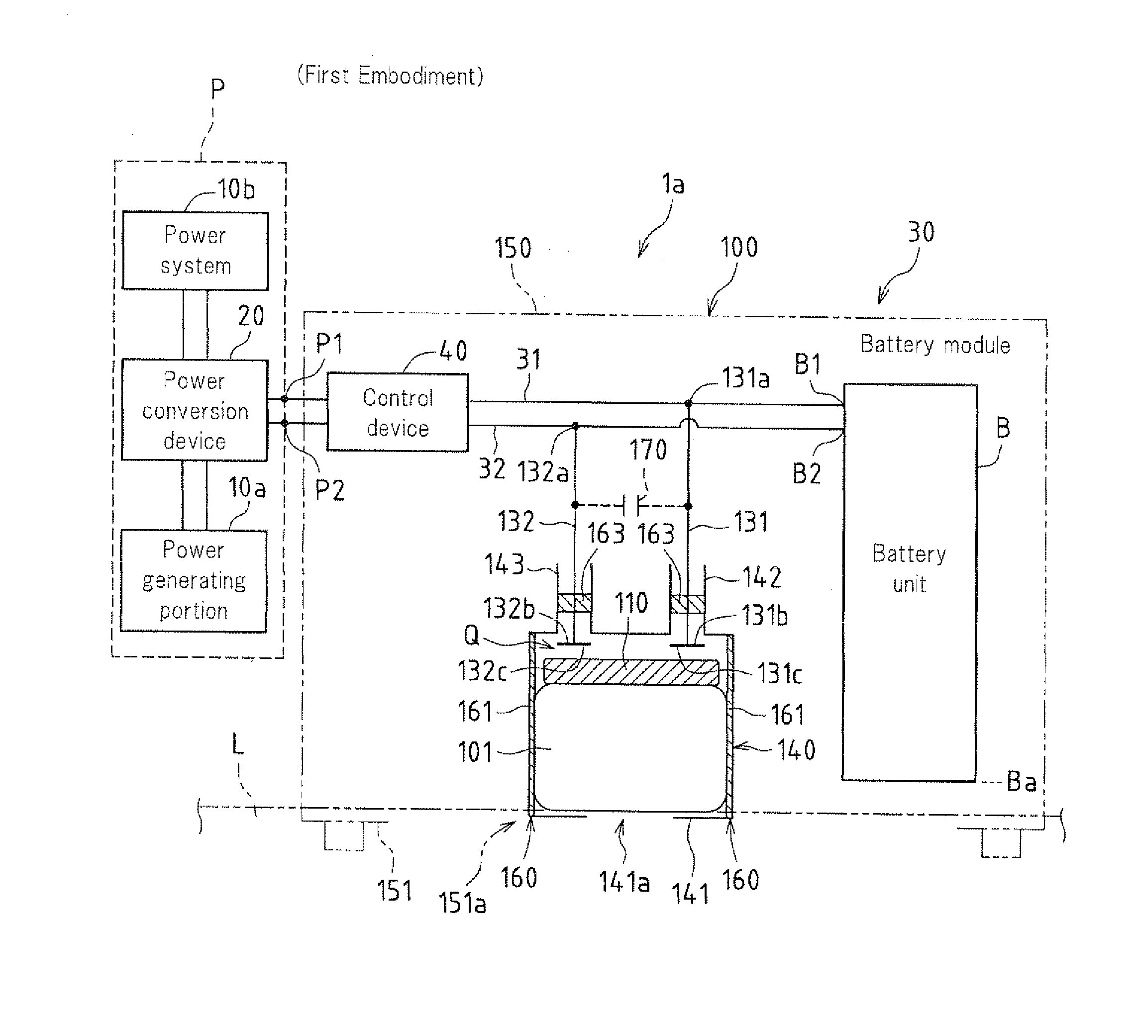
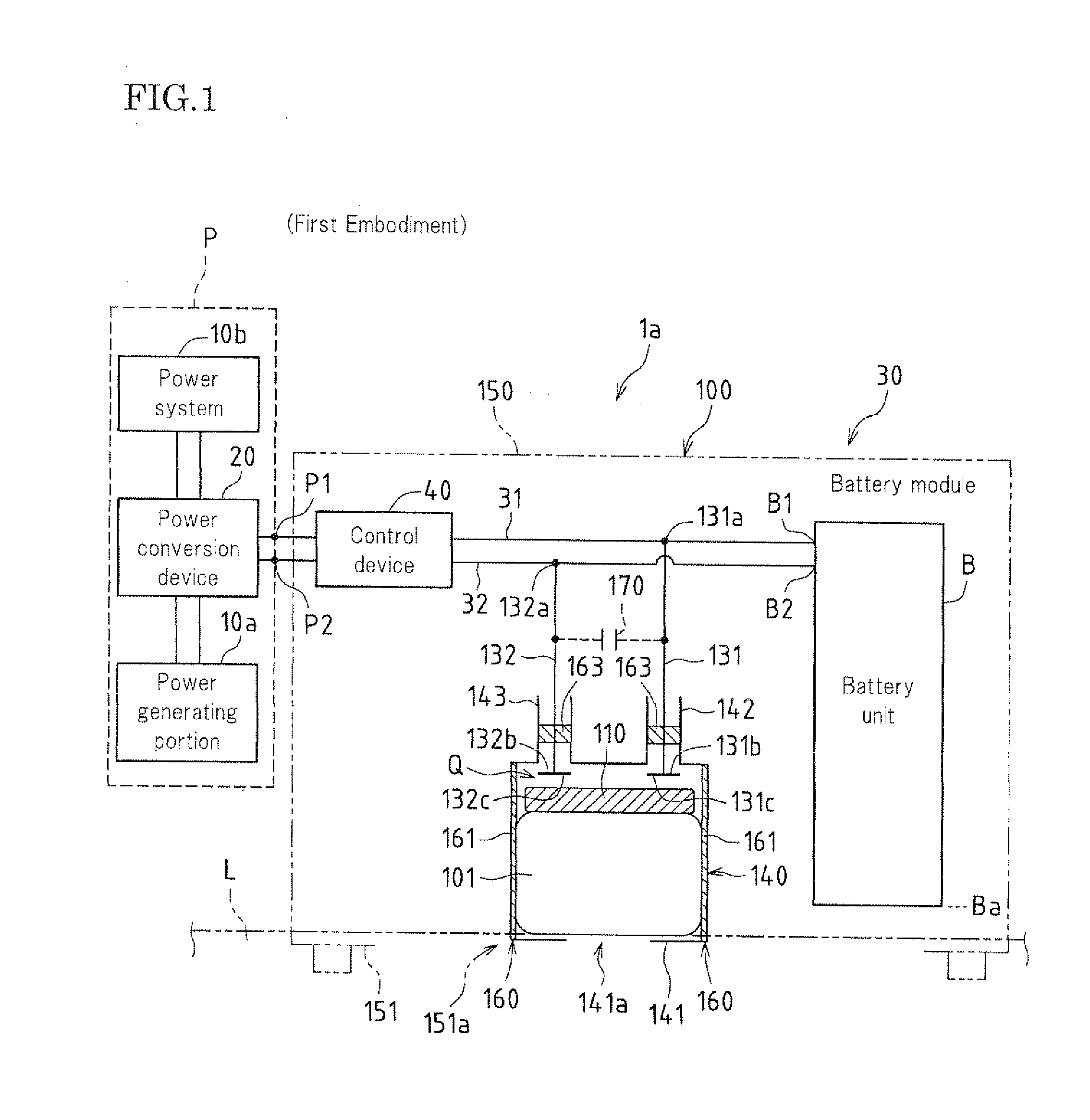
[0132]FIG. 1 is a diagram showing an example in which a forced discharge mechanism 100 for a storage battery B according to a first embodiment of the present invention is applied to a power generation system 1a.

[0133]The power generation system 1a shown in FIG. 1 converts direct current power from a power generating portion 10a into alternating current power in a power conversion device 20 (here, inverter), supplies the alternating current power obtained by conversion to a power system lob, and is interconnected with the power system 10b. Further, the power generation system 1a supplies direct current power from the power generating portion 10a to the storage battery B. Note that the power generating portion 10a, the power system 10b, and the power conversion device 20 operate as an external power source P.

[0134]The power generating portion 10a may be an electric power device such as a solar cell that directly converts natural energy such as sunlight into electric power or an elect...

second embodiment

[0184]FIG. 5 is a diagram showing an example in which a safety switch device 200a according to a second embodiment of the present invention is applied to a power generation system 1b.

[0185]The power generation system 1b shown in FIG. 5 is provided with the safety switch device 200a in the power generation system 1a shown in FIG. 1.

[0186]In the power generation system 1b according to the second embodiment shown in FIG. 5, the same constituent elements as in the power generation system 1a according to the first embodiment shown in FIG. 1 are given the same reference numerals, and the description thereof is omitted. The same also applies to the third to seventh embodiments shown in FIGS. 7 to 11 that will be described later.

[0187]The safety switch device 200a is provided with an interrupting device 210a capable of interrupting the connection between the external power source P and conduction portions (points where the paths branch to the discharge paths 131 and 132) 31a and 32a on the...

third embodiment

[0201]FIG. 7 is a diagram showing an example in which a safety switch device 200b according to a third embodiment of the present invention is applied to a power generation system 1c.

[0202]The power generation system 1c shown in FIG. 7 is obtained by providing the power generation system 1b shown in FIG. 5 with an interrupting device 210b, instead of the interrupting device 210a. Further, the interrupting device 210b is obtained by providing the interrupting device 210a with a current flow detection sensor 50b, instead of the water detection sensor 50a.

[0203]The current flow detection sensor 50b is connected in series to at least one of the discharge paths 131 and 132 (here, the discharge path 132), and is connected to the input system of the control device 40. Here, the current flow detection sensor 50b is a current detector.

[0204]With the safety switch device 200b according to the third embodiment, in the forced discharge mechanism 100, the float portion 101 rises up, the electri...


PUM


Abstract

A forced discharge mechanism for a storage battery for forcibly establishing conduction between a pair of power transport paths that are respectively connected to a positive electrode terminal and a negative electrode terminal of the storage battery includes an electric resistor for establishing conduction between the power transport paths, and the electric resistor is movable due to a buoyant force of liquid that has entered.

Description

BACKGROUND OF THE INVENTION[0001]This application claims priority under 35 U.S.C. §119(a) on Patent Application No. 2009-272252 filed in Japan on Nov. 30, 2009, the entire contents of which are herein incorporated by reference.[0002]The present invention relates to a forced discharge mechanism for a storage battery and a safety switch device, such as, for example, a forced discharge mechanism for a storage battery and a safety switch device that are provided in a battery module having a protective function.[0003]Examples of a conventional storage battery (secondary battery) include a battery module having a protective function that operates when an abnormal condition occurs.[0004]As an example of such a battery module having a protective function, a battery module having a protective function that operates when an abnormal condition such as getting wet occurs is described below.[0005]For example, storage batteries in battery modules that are used outdoors have become rapidly widespr...

Claims


Application Information

Patent Timeline
IPC IPC(8): H01M10/46H02J7/00H01H9/54H01H35/18H01M8/00H01M10/42H01M10/44H01M10/60H01M10/613H01M10/625H01M10/627H01M50/574H02H5/00H02H7/18
CPCH01M2/34H01M10/44H02J7/0031H01M10/48H01M10/465Y02E60/10H01M50/574H02H7/18H02H5/04
Inventor YONEDA, TETSUYA
Owner SHARP KK
Why Eureka
Try Eureka