Wireless power system

a power system and wireless technology, applied in the field of power conversion, can solve the problems of not being able to wirelessly power the device itself, compatibility issues between different vendors' wireless power products, and still significant effort needed to make cost-effective and/or feature-rich wireless power systems

Inactive Publication Date: 2011-06-02
KONINKLJIJKE PHILIPS NV
View PDF17 Cites 155 Cited by
  • Summary
  • Abstract
  • Description
  • Claims
  • Application Information

AI Technical Summary

Problems solved by technology

Thus, the device itself cannot be wirelessly powered without the receive unit coupled to it.
While the above referenced standards organization are attempting to establish standards regarding the control channel protocol, currently, vendors are free to use whatever pro...

Method used


Image

  • Wireless power system
  • Wireless power system
  • Wireless power system

Examples


Embodiment Construction

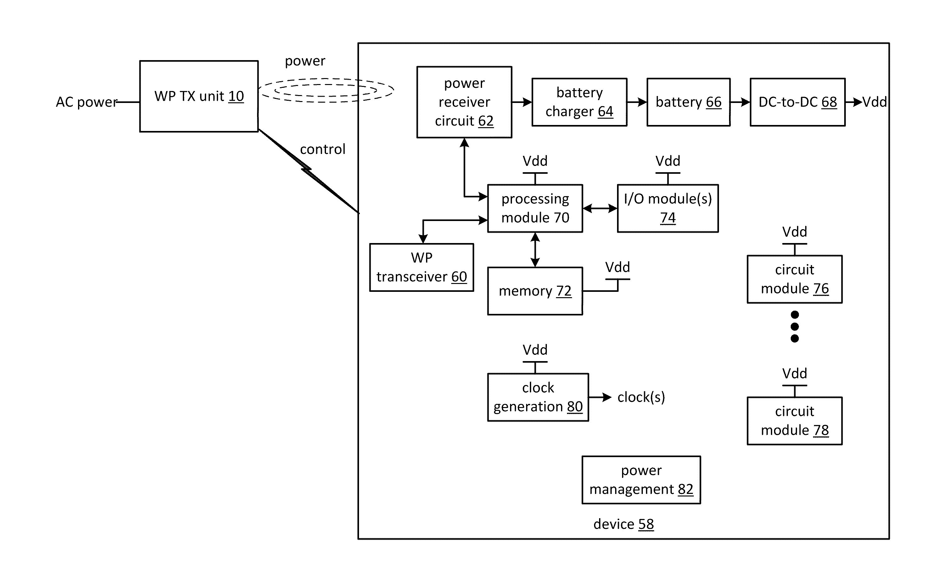
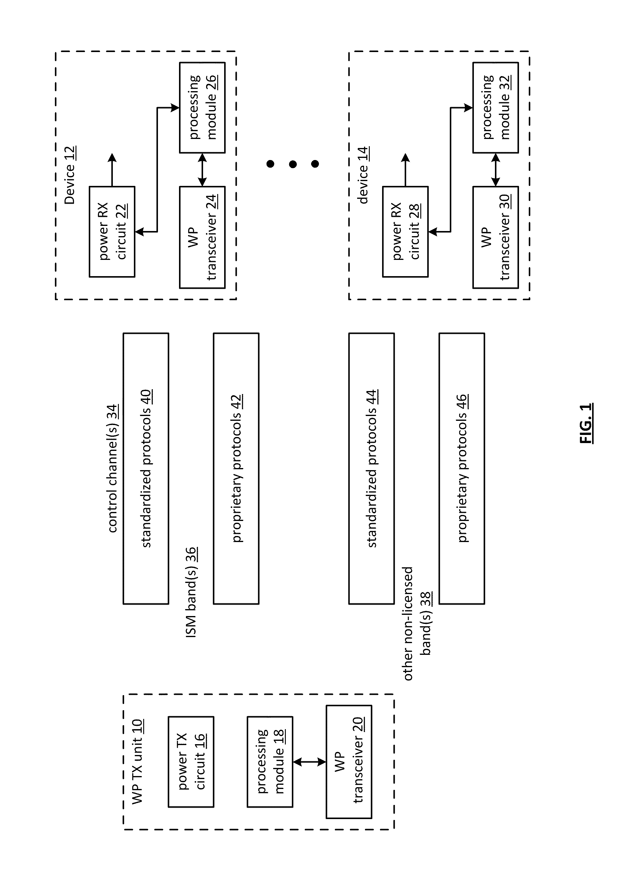
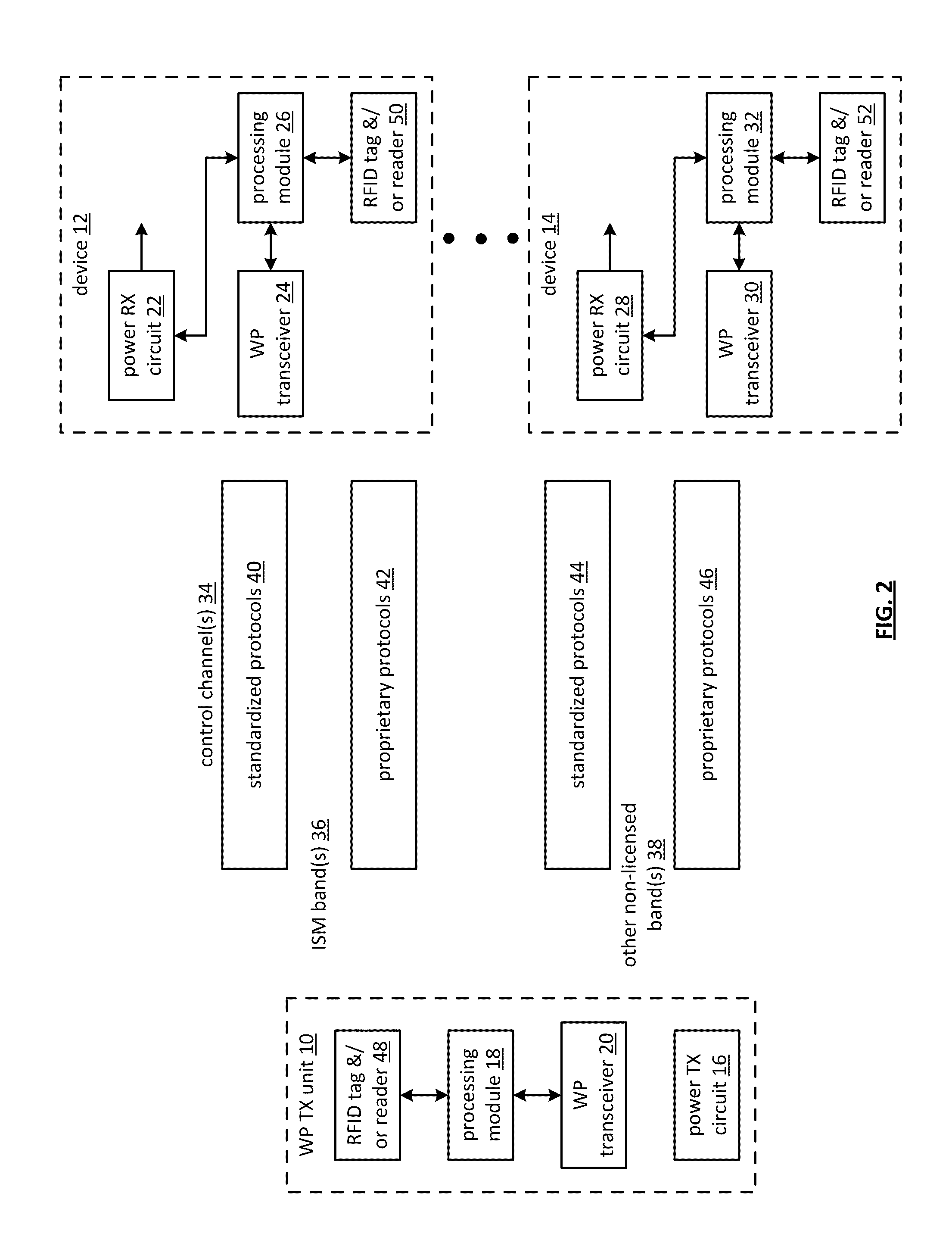
[0082]FIG. 1 is a schematic block diagram of an embodiment of a wireless power system that includes a wireless power (WP) transmit (TX) unit 10 and one or more devices 12-14. The WP TX unit 10 includes a processing module 18, a WP transceiver 20, and a power TX circuit 16. Each device 12-14 includes a WP receive (RX) circuit 22, 28, a processing module 26, 32, and a WP transceiver 24, 30. The device 12-14 will most likely include a plurality of other components depending on its desired functionality. For example, the device 12-14 may be a cell phone, a personal audio / video player, a video game unit, a toy, etc. and includes the corresponding circuitry.

[0083]The processing modules 18, 26, 32 of the WP TX unit 10 and in each of the devices 12-14 may each be a single processing device or a plurality of processing devices. Such a processing device may be a microprocessor, micro-controller, digital signal processor, microcomputer, central processing unit, field programmable gate array, p...


PUM


Abstract

A wireless power system includes a primary device and a secondary device. The primary device includes a power conversion unit, a function module, and a transceiver. The peripheral device includes a wireless power receiver circuit, a peripheral transceiver, and a peripheral unit. The power conversion unit converts a power source into an electromagnetic signal. The functional module executes a function regarding peripheral information. The transceiver communicates information regarding the electromagnetic signal and the peripheral information. The wireless power receiver circuit converts the electromagnetic signal into a voltage. The peripheral transceiver communicates the information regarding the electromagnetic signal and the peripheral information. The peripheral unit processes the peripheral information.

Description

[0001]This patent application is claiming priority under 35 USC §119 to a provisionally filed patent application entitled WIRELESS POWER SYSTEMS AND METHODS, having a provisional filing date of Nov. 30, 2009, and a provisional Ser. No. 61 / 264,925.STATEMENT REGARDING FEDERALLY SPONSORED RESEARCH OR DEVELOPMENT[0002]Not ApplicableINCORPORATION-BY-REFERENCE OF MATERIAL SUBMITTED ON A COMPACT DISC[0003]Not ApplicableBACKGROUND OF THE INVENTION[0004]1. Technical Field of the Invention[0005]This invention relates to power conversion and more particularly to wireless power conversion and supporting communications thereof.[0006]2. Description of Related Art[0007]The concept of wireless power (i.e., powering a device without an electrical power cord) has been around for a while and has recently been commercialized. In addition, there are a couple of on-going standards discussions (WPC—wireless communication alliance and CEA—consumer electronics association) to standardize wireless power syst...

Claims


Application Information

Patent Timeline
IPC IPC(8): H02J7/00H02J17/00
CPCG06K7/10207G06K7/10346G06K19/0701G06K19/0715H04L29/06163H02J17/00H04B5/0037H02J7/025H04L69/18G06K19/0723H02J50/12H02J50/80H02J50/10
Inventor WALLEY, JOHNKARAOGUZ, JEYHANSESHADRI, NAMBIRAJANVAN DER LEE, REINIER
Owner KONINKLJIJKE PHILIPS NV
Why Eureka
Try Eureka