Time domain reflectometer touch screen sensor

a technology of reflectometer and touch screen, applied in the direction of instruments, electric digital data processing, input/output processes of data processing, etc., can solve the problems of reducing the brightness of the overall display, bulky whole unit, and limited technology to small handheld type of applications, etc., to achieve the effect of multi-touchabl

Inactive Publication Date: 2011-06-02
KIM KIHONG JOSHUA
View PDF13 Cites 49 Cited by
  • Summary
  • Abstract
  • Description
  • Claims
  • Application Information

AI Technical Summary

Benefits of technology

[0012]The major difference between the present invention and prior arts of capacitive touch sensor is that TDR method is using one dimensional sensor to locate a point in a two dimensional plane by the help of time domain information. In other words, TDR does not require 2nd dimension axis to define (se

Problems solved by technology

This invention, however, unless LCD panel manufacturer invest on embedded sensor array in TFT(Thin Film Transistor)—LCD array process, create extra volume to place the external camera at least in its focal distance to capture the image properly so that it makes the whole unit bulky which is not desirable for their thinner and wall-mountable purpose.
(FIG. 3) But because PCT uses ITO (indium tin oxide) metal layer on glass or in general any transparent material such as acrylic board, the brightness of overall display is diminished due to its opaqueness.
This becomes why the technology is limited to t

Method used


Image

  • Time domain reflectometer touch screen sensor
  • Time domain reflectometer touch screen sensor
  • Time domain reflectometer touch screen sensor

Examples


Embodiment Construction

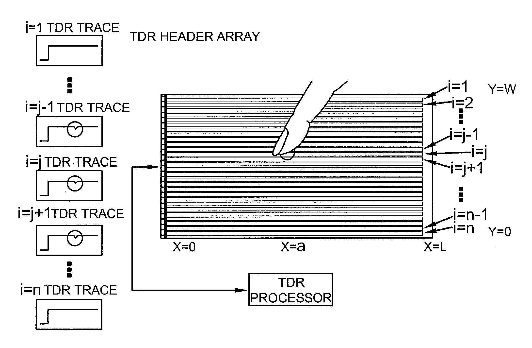
[0032]The present invention described in this patent application uses Time Domain Reflection (TDR) technology. TDR is well known and matured technology and is actively used for the characterization of various passive electrical components as well as transmission lines or simple PCB (Printed Circuit Board) conducting trace especially to characterize its high speed electronic signal integrity. For instance, it can be used to locate discontinuities or areas of higher resistance within a conductor.

[0033]TDR transmits a short rise time pulse along the conductor. If the conductor is of uniform impedance and properly terminated, the entire transmitted pulse will be absorbed in the far-end termination and no signal will be reflected toward the TDR. Any impedance discontinuities will cause some of the incident signal to be sent back towards the source. This is similar in principle to radar.

[0034]Increases in the impedance create a reflection that reinforces the original pulse while decreases...


PUM


Abstract

TDR (time domain reflection) technology may be used in optical domain or in electrical domain. For electrical TDR, single layer ITO glass may form a transmission line as a base TDR touch sensor. When the touch sensor is paired, the existing internal metal line of the display device may be reused as a TDR sensor and the ITO glass may be removed. When touched, the TDR profile is changed dynamically from baseline to the particular profile due to its dynamic impedance profile change across the display screen. Likewise, for optical TDR touch sensing, 2 dimensional optical slab waveguide is used to carry OTDR signal. When touched, the profile is changed due to this perturbation mainly by evanescent field changes on that particular position.

Description

[0001]This application claims priority from U.S. Provisional Ser. No. 61 / 265,288, entitled TIME DOMAIN REFLECTOMETER TOUCH SCREEN SENSOR, filed Nov. 29, 2009, and U.S. Provisional Ser. No. 61 / 264,831, entitled OPTICAL REFLECTOMETER TOUCH SCREEN SENSOR, filed Nov. 29, 2009, both which are incorporated herein by reference.I. BACKGROUND OF THE INVENTION[0002]A. Field of Invention[0003]The present invention relates generally to touch-screen displays, and more specifically to a high-resolution touch screen display with multi-touch capability either using electrical time domain reflection or optical time domain reflection profile.[0004]B. Description of the Related Art[0005]There are about a dozen technologies available in the field of touch screen sensor that applies onto display unit such as LCD (Liquid Crystal Display), CRT, and Plasma display and so on. ATM machine display unit and MP3 display in a consumer product are well known daily encountered examples of the field. Recently as a ...

Claims


Application Information

Patent Timeline
IPC IPC(8): G06F3/042G06F3/041
CPCG06F3/041G06F3/044G06F3/0425G06F3/0446G06F3/0445G06F3/04166
Inventor KIM KIHONG (JOSHUA)
Owner KIM KIHONG JOSHUA
Why Eureka
Try Eureka