Driving circuit for light emitting diode

a technology of light-emitting diodes and driving circuits, which is applied in the direction of electric variable regulation, process and machine control, instruments, etc., can solve the problems of poor efficiency, deterioration of feedback precision, and violation of electrical isolation requirements

Active Publication Date: 2011-06-02
ROHM CO LTD
View PDF6 Cites 62 Cited by
  • Summary
  • Abstract
  • Description
  • Claims
  • Application Information

AI Technical Summary

Benefits of technology

[0033]With such an embodiment, when the driving current to be supplied to the light emitting diode is ON, and an abnormal state is detected, time counting is performed for the circuit protecting operation. Thus, such an arrangement is capable of distinguishing between the OFF state of the driving current and an abnormal state. Furthermore, such a

Problems solved by technology

Such an arrangement requires two-step voltage conversion, leading to poor efficiency.
However, in such an arrangement, the feedback line straddles the hot region HOT and the cold regio

Method used


Image

  • Driving circuit for light emitting diode
  • Driving circuit for light emitting diode
  • Driving circuit for light emitting diode

Examples


first embodiment

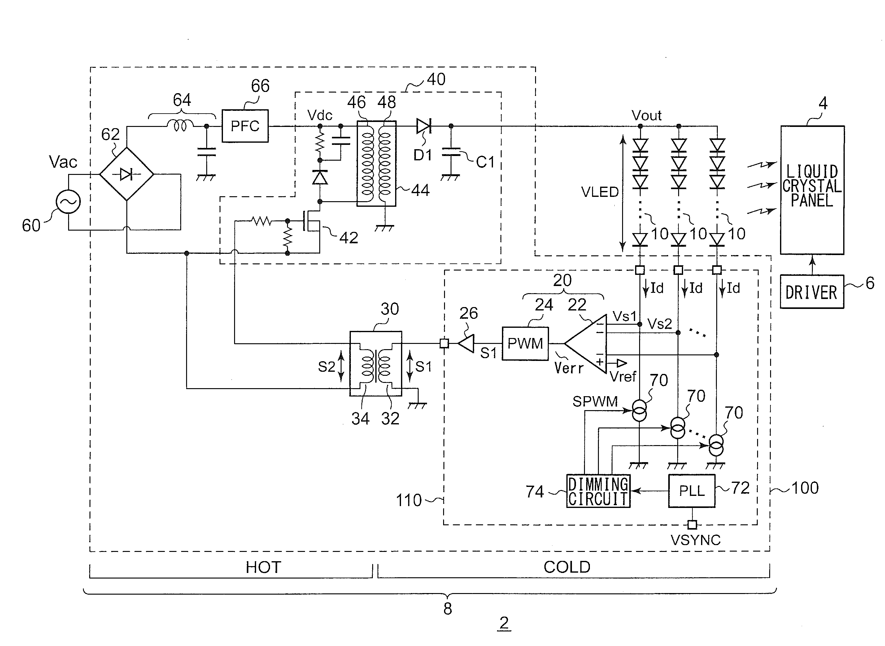
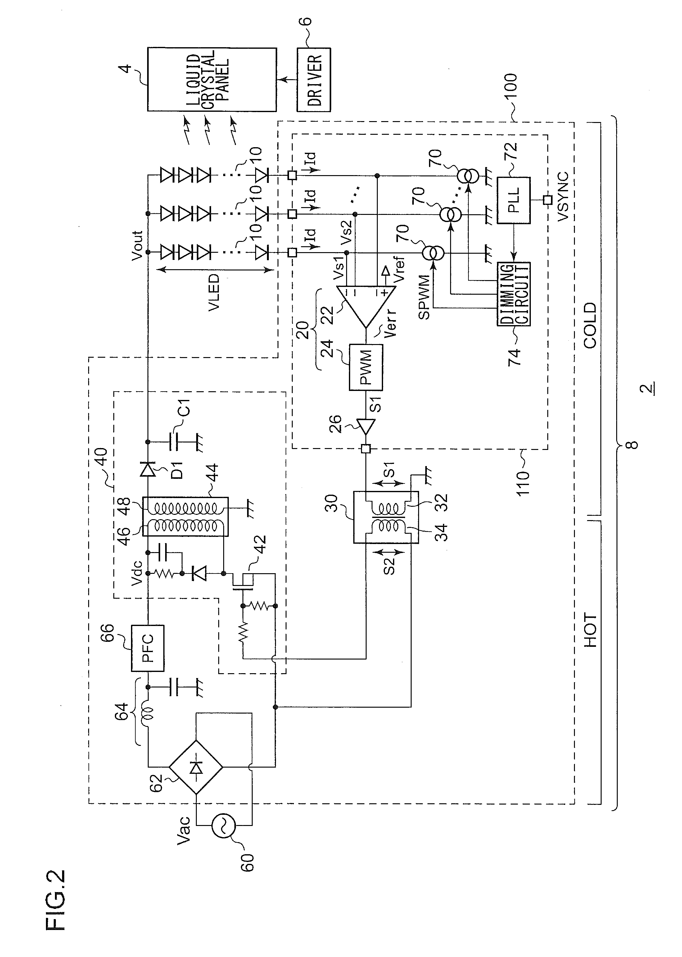
[0048]FIG. 2 is a circuit diagram which shows a configuration of a display apparatus 2 according to a first embodiment. The display apparatus 2 includes a liquid crystal panel 4, a liquid crystal driver 6, and a backlight 8.

[0049]The liquid crystal panel 4 includes multiple pixels arranged in the form of a matrix. The respective pixels are arranged at the points of intersection of the multiple data lines and the multiple scanning lines. The liquid crystal driver 6 receives image data to be displayed on the liquid crystal panel 4. The liquid crystal driver 6 includes a data driver which applies a driving voltage to the multiple data lines according to the luminance level, and a gate driver which sequentially selects the multiple scanning lines.

[0050]The backlight 8 is arranged on the back face of the liquid crystal panel 4. The backlight 8 includes multiple LED strings 10 and a driving circuit 100 configured to drive the multiple LED strings 10. Each LED string 10 includes multiple L...

second embodiment

[0080]FIG. 6 is a circuit diagram which shows a configuration of an LED driving circuit 100 according to a second embodiment. FIG. 6 shows the overall configuration of an light emitting apparatus including the LED driving circuit 100 and an LED string 10. Such a light emitting apparatus can be used for various applications employing LEDs, such as a backlight for a liquid crystal panel, illumination for a cellular phone, and an illumination apparatus. The second embodiment according to the present invention can be used in combination with the first embodiment, or can be used as a standalone apparatus.

[0081]The LED driving circuit 100 includes a power supply circuit 40 and an LED driving IC 110, and drives an LED string 10 including at least one LED. The power supply circuit 40 includes at least one of a switching regulator, a charge pump circuit, and a linear regulator, or a combination thereof. The power supply circuit 40 generates a driving voltage Vdrv required to drive the LED st...


PUM


Abstract

A pulse modulator generates a first pulse signal having a duty ratio which is adjusted such that a detection voltage which indicates the electrical state of an LED string to be driven matches a predetermined reference voltage. A first pulse signal is applied to a primary coil of a pulse transformer. A DC/DC converter includes a switching element the ON/OFF operation of which is controlled according to a signal that originates at a secondary coil of the pulse transformer. The DC/DC converter stabilizes an input voltage Vdc, and supplies the input voltage Vdc thus stabilized to the anode of the LED string.

Description

BACKGROUND OF THE INVENTION[0001]1. Field of the Invention[0002]The present invention relates to a driving technique for a light emitting diode.[0003]2. Description of the Related Art[0004]As a backlight for a liquid crystal panel, white light emitting diodes (which will be simply referred to as “LEDs” hereafter) having improved properties from the perspective of a long operating life, low power consumption, and a wide color range are employed instead of conventional CCFLs (Cold Cathode Fluorescent Lamps) or EEFLs (External Electrode Fluorescent Lamps).RELATED ART DOCUMENTSPatent Documents[0005][patent document 1][0006]Japanese Patent Application Laid Open No. 2004-32875[patent document 2][0007]Japanese Patent Application Laid Open No. 2002-252971[patent document 3][0008]Japanese Patent Application Laid Open No. 2007-028784[patent document 4][0009]Japanese Patent Application Laid Open No. 2007-173813[patent document 5][0010]Japanese Patent Application Laid Open No. 2008-136293[0011]...

Claims


Application Information

Patent Timeline
IPC IPC(8): G09G5/10H05B37/02G09G3/36H05B44/00
CPCG09G3/3406G09G2310/08G09G2320/064Y02B20/347Y02B20/341H05B33/0818H05B33/0887H05B33/0827H05B45/46Y02B20/30H05B45/385
Inventor YONEMARU, MASAOINOUE, NAOKIISHIKAWA, HIROYUKI
Owner ROHM CO LTD
Why Eureka
Try Eureka