Fluid mixer and apparatus using fluid mixer

a technology of fluid mixer and mixer, which is applied in the direction of gaseous fuels, transportation and packaging, fuels, etc., can solve the problems of large space for providing branched pipelines, large number of parts, and complicated installation of such pipelines, so as to prevent burns, prevent defects, and stabilize the temperature more

Active Publication Date: 2011-06-02
ASAHI YUKIZAI KOGYO CO LTD
View PDF7 Cites 37 Cited by
  • Summary
  • Abstract
  • Description
  • Claims
  • Application Information

AI Technical Summary

Benefits of technology

(1) Even in a state where the concentration of a chemical temporarily becomes denser or thinner in a flow path, it is possible to mix the fluid while making the distribution of concentration of the fluid in the direction of flow uniform without any unevenness, possible to supply a chemical in a stable concentration, and possible to prevent defects due to changing concentrations of chemicals in various industrial fields.
(2) Even in a state in which the temperature of the fluid temporarily becomes hig...

Problems solved by technology

In this case, there was the problem of the space for providing the branched pipelines ending up becoming larger.
Further, ther...

Method used


Image

  • Fluid mixer and apparatus using fluid mixer
  • Fluid mixer and apparatus using fluid mixer
  • Fluid mixer and apparatus using fluid mixer

Examples


first embodiment

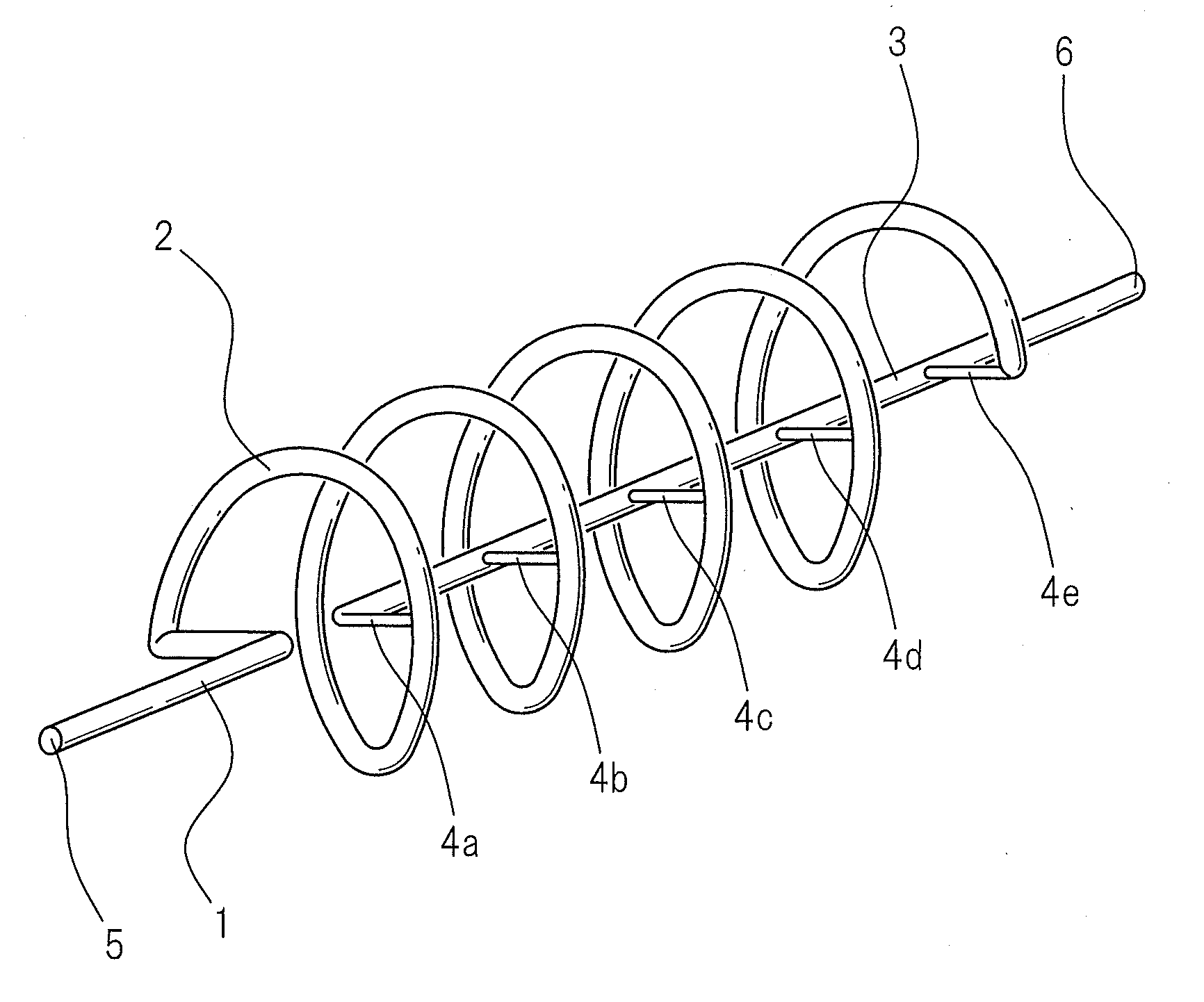
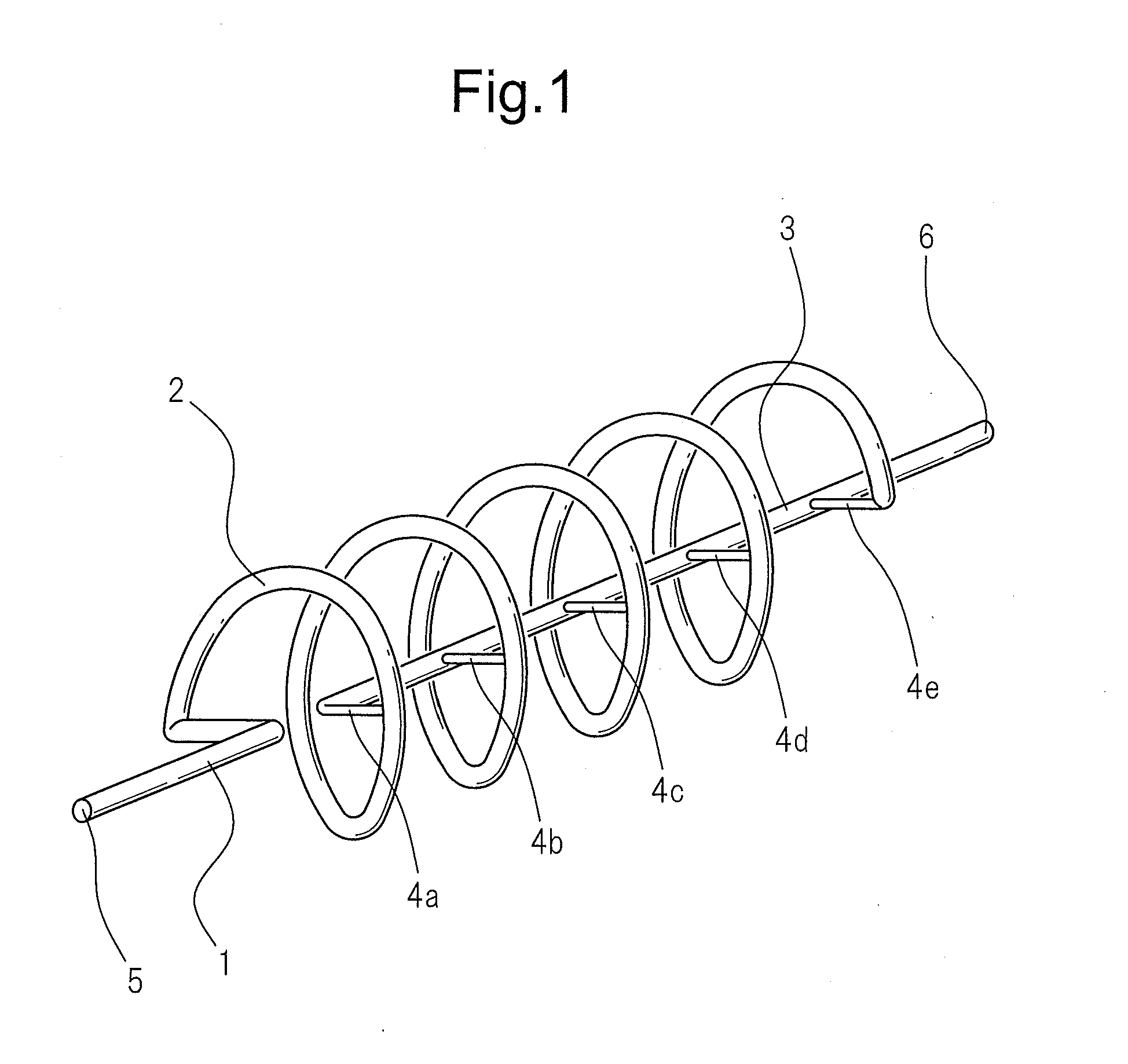
Below, embodiments of the present invention will be described with reference to the embodiments shown in the drawings, but the present invention is not limited to these embodiments needless to say. Below, referring to FIG. 1, a fluid mixer of the present invention will be explained.

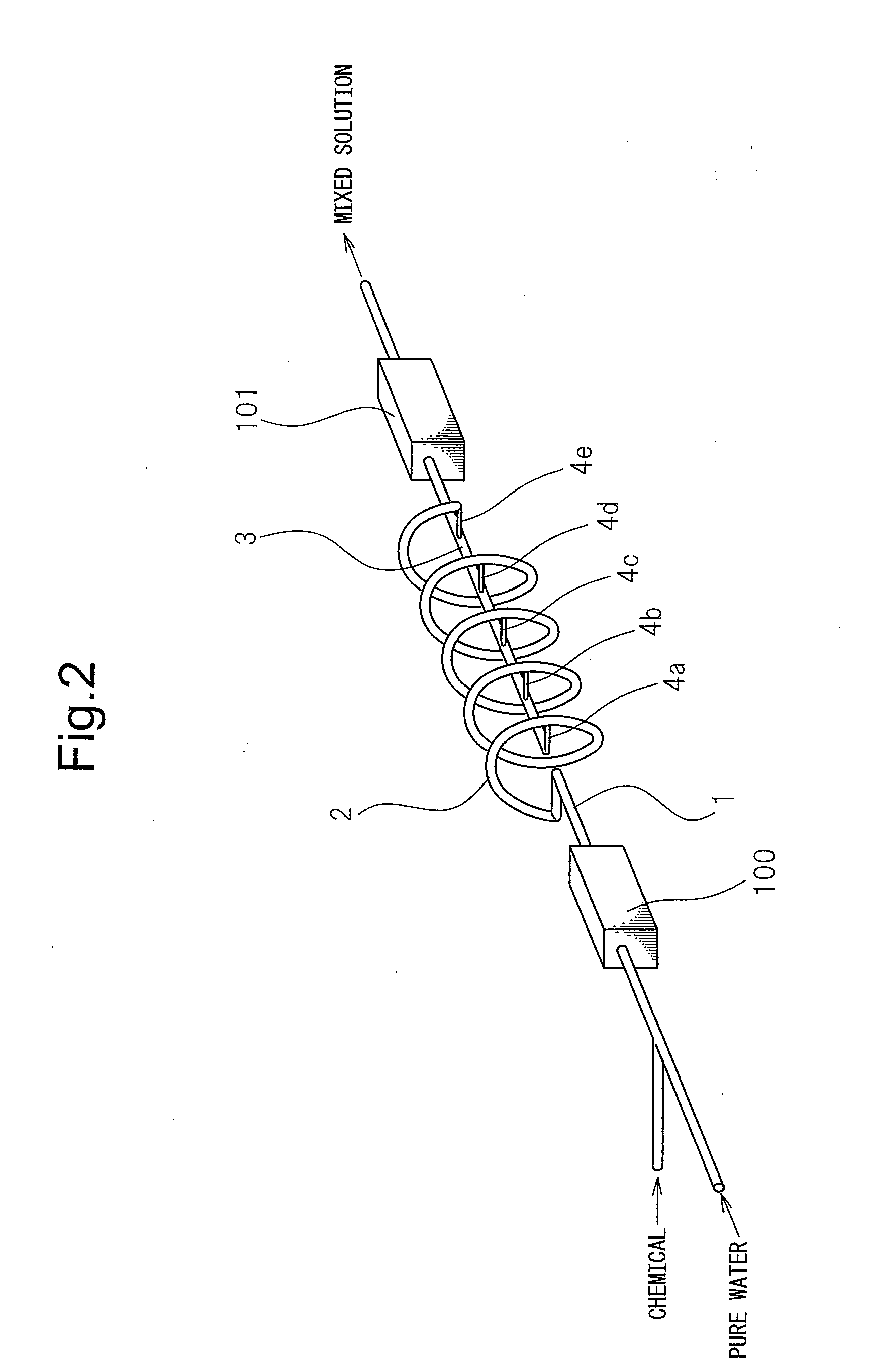
The fluid mixer is provided with a fluid inlet 5 into which the fluid flows, a first flow path 1 connected to the fluid inlet 5, a fluid outlet 6 from which the fluid flows, and a second flow path 3 connected to the fluid outlet 6—all on the same axis—and a spiral flow path 2 having the flow paths 1 and 3 as the center axis of the spiral. The first flow path 1 and the second flow path 3 are both straight flow paths. At one end part of the spiral flow path 2, the first flow path 1 is connected. In the middle of the spiral flow path 2, five branch flow paths 4a to 4e are provided connected to the second flow path 3. Further, the branch flow path 4e positioned at the location nearest to the fluid outlet 6 si...

second embodiment

Next, referring to FIG. 5, the fluid mixer of the present invention will be explained.

Reference numeral 7 is a PTFE main body part. The main body part 7 is formed into a columnar shape. At one end face of the main body part 7, a fluid inlet 8 and a first flow path 9 connected to the fluid inlet 8 are connected. At the other end face, a fluid outlet 10 and a second flow path 11 connected to the fluid outlet 10 is provided. The first and second flow paths 9 and 11 are arranged at positions on the center axis of the main body part 7. At the outer circumferential surface of the main body part 7, a spiral groove 12 is provided. One end part of the spiral groove 12 is connected to the first flow path 9. Communicating holes 13 forming a plurality of branch flow paths are provided communicating the inner circumferential surface of the second flow path 11 and the bottom surface of the spiral groove 12. Further, the communicating hole 13 positioned at the location nearest the fluid outlet 10 ...

third embodiment

Next, referring to FIG. 9, a fluid mixer of the present invention will be explained.

The fluid mixer is provided with a fluid outlet 46 from which the fluid flows out, a second flow path 43 connected to the fluid outlet 46, and a spiral flow path 42 having the second flow path 43 as the center axis of the spiral. A fluid inlet 45 into which the fluid flows and a first flow path 41 connected to the fluid inlet 45 are provided connected with one end part of the spiral flow path 42 at the fluid outlet side. In the middle of the spiral flow path 42, five branch flow paths 44a to 44e are provided connected with the second flow path 43. Further, the branch flow path 443 positioned at the location furthest from the fluid outlet 46 side is provided connected to the other end part of the spiral flow path 42. In this embodiment, for example, tubes etc. may be used for pipe connections.

Next, the action of the fluid mixer of the third embodiment of the present invention will be explained.

From th...


PUM

PropertyMeasurementUnit
Temperatureaaaaaaaaaa
Diameteraaaaaaaaaa
Concentrationaaaaaaaaaa

Abstract

A fluid mixer which can mix fluid while making the distribution of concentration or distribution of temperature of the fluid in the direction of flow uniform without any unevenness and which is both compact and easy to install piping for is provided. This fluid mixer has a fluid inlet, a first flow path connected to the fluid inlet, a spiral flow path connected to the first flow path, a plurality of branch flow paths branched from the spiral flow path, a second flow path to which the plurality of branch flow paths are connected, and a fluid outlet connected to the second flow path, the plurality of branch flow paths branching from different positions of the spiral flow path and being connected with the second flow path at different positions of the second flow path.

Description

TECHNICAL FIELDThe present invention relates to a fluid mixer used for fluid transport piping in various industrial fields such as chemical factories, the semiconductor production field, food field, medical field, biotech field, etc., in particular relates to a fluid mixer and apparatus using a fluid mixer able to mix fluid while making the distribution of concentration or distribution of temperature of the fluid in the direction of flow uniform without any unevenness.BACKGROUND ARTIn the past, as the method of attaching a device inside of a pipe to uniformly mix fluid flowing through the inside of the pipe, as shown in FIG. 16, use of a swirl blade type static mixer element 81 has been the general practice (see, for example, Japanese Patent Publication (A) No. 2001-205062). Usually, the static mixer element 81 is comprised of a square plate twisted 180 degrees about its longitudinal axis as a minimum unit member and has a plurality of such minimum unit members integrally connected ...

Claims


Application Information

Patent Timeline
IPC IPC(8): B01F5/00B01F23/00B01F23/10B01F23/30
CPCB01F5/0614B01F5/0644C10L3/00B01F5/0647B01F5/0646B01F25/4314B01F25/4323B01F25/4331B01F25/433C10L1/32B01F23/00B01F25/00
Inventor HANADA, TOSHIHIRO
Owner ASAHI YUKIZAI KOGYO CO LTD
Why Eureka
Try Eureka