Image forming apparatus using plurality of rotation members, and control method thereof

a technology of rotating members and forming apparatus, which is applied in the direction of electrographic process apparatus, instruments, optics, etc., can solve problems such as forming defective images

Inactive Publication Date: 2011-06-02
CANON KK
View PDF10 Cites 13 Cited by
  • Summary
  • Abstract
  • Description
  • Claims
  • Application Information

AI Technical Summary

Benefits of technology

[0007]An image forming apparatus includes first and second rotation members which are a plurality of rotation members for performing image formation and rotate in contact with each other. A first driving motor drives the first rotation member. A second driving motor drives the second rotation member. The obtaining unit obtains pieces of motor driving information about driving states of the first or second driving motor at respective relative driving speeds when the relative driving speed of the second driving motor with respect to the driving speed of the first driving motor is changed to a plurality of relative driving speeds. The control unit controls the driving speed of at least either the first or second driving motor in image formation to reduce the relative speed difference between the circumferential velocities of the first and second rotation members based on the pieces of motor driving information obtained by the obtaining unit.

Problems solved by technology

This is because, if their rotational speeds are neither the same nor almost the same, the frictional force between the rotation members will not act properly on toner or a print sheet entering the nip, forming a defective image.

Method used


Image

  • Image forming apparatus using plurality of rotation members, and control method thereof
  • Image forming apparatus using plurality of rotation members, and control method thereof
  • Image forming apparatus using plurality of rotation members, and control method thereof

Examples


first embodiment

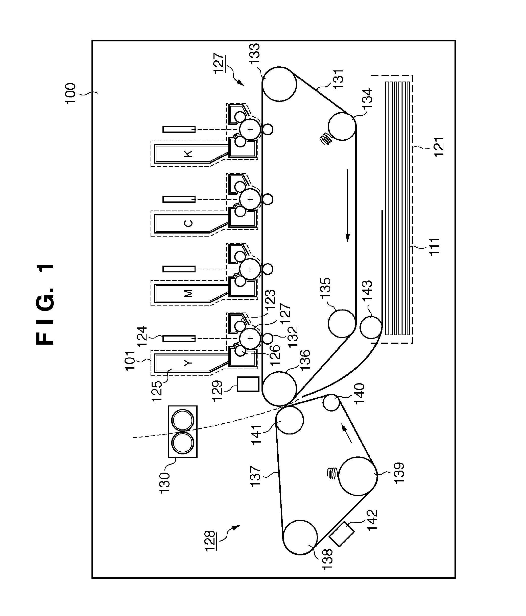
[0046]FIG. 1 is a sectional view showing the schematic structure of an image forming apparatus. An image forming apparatus 100 forms an image using an electro-photographic process. Note that the image forming apparatus in the present invention may form an image using an electrostatic printing process or magnetic printing process. An example of the developer is toner formed from, for example, a heat fusible resin. Examples of the print medium are print paper, transfer sheet, OHT sheet, glossy paper, glossy film, electrofax paper, and electrostatic print paper. The image forming apparatus 100 forms a multicolor image using four, yellow (Y), magenta (M), cyan (C), and black (K) color toners. Note that the present invention is also applicable to a monochrome image forming apparatus.

[0047]The image forming apparatus 100 includes four cartridges 101. Each cartridge 101 includes a photosensitive member 122, charging sleeve 123, toner container 125, and developing sleeve 126. The photosensi...

second embodiment

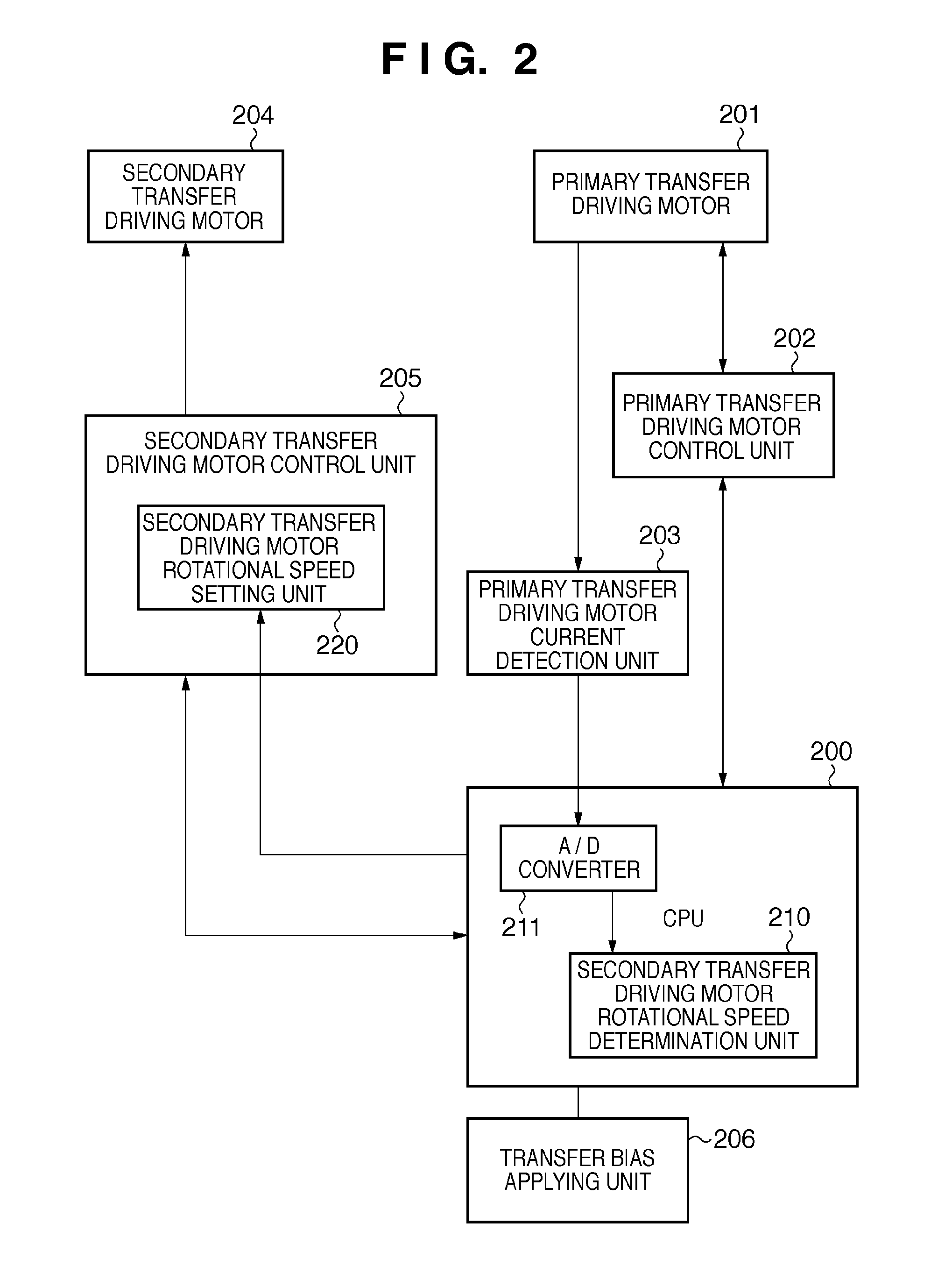
[0083]The second embodiment will describe an invention in which, while applying a secondary transfer bias to a secondary transfer belt 137, the current value of a primary transfer driving motor 201 is detected to control the target rotational speed of a secondary transfer driving motor 204.

[0084]FIGS. 8A and 8B are flowcharts showing a control sequence executed by a CPU 200. The same reference symbols as those in FIG. 6 denote the same processes to simplify the description. In FIG. 8A, S801 is inserted between S605 and S606 in FIG. 6. Also, S802 to S809 replace S616.

[0085]In S801, the CPU 200 instructs a bias applying unit 206 to apply the secondary transfer bias. In response to this, the bias applying unit 206 starts applying the secondary transfer bias. The secondary transfer bias is positive when transferring a toner image from a primary transfer belt 131 onto a print sheet 111, and negative in cleaning. In S801, a positive bias is applied. In S606, the current of the primary tra...

third embodiment

[0093]In the first or second embodiment, the rotational speed of the secondary transfer driving motor 204 is controlled by detecting the current value of the primary transfer driving motor 201. However, when the motor current of the secondary transfer driving motor 204 draws a linear characteristic with respect to the load, the rotational speed of the secondary transfer driving motor 204 can be controlled by detecting the current value of the secondary transfer driving motor 204. A method of controlling the rotational speed of the secondary transfer driving motor 204 by detecting the current value of the secondary transfer driving motor 204 is applicable to both the first and second embodiments, and an application to the first embodiment will be explained below.

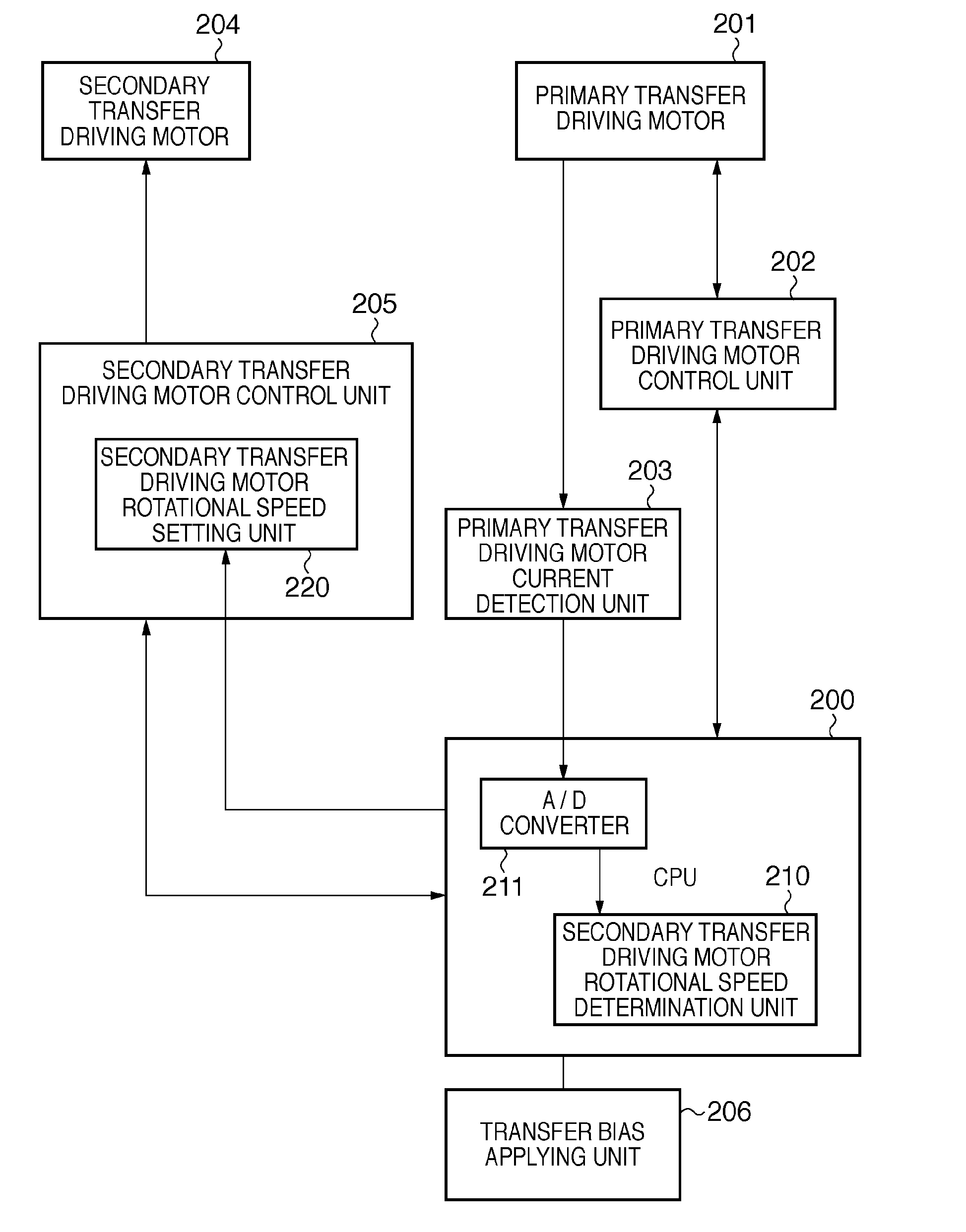
[0094]FIG. 10 is a block diagram showing the control circuit of an image forming apparatus according to the third embodiment. The same reference numerals as those in FIG. 2 denote the same parts, and a description thereof wil...


PUM


Abstract

An image forming apparatus includes first and second rotation members which are a plurality of rotation members for performing image formation and rotate in contact with each other. A first driving motor drives the first rotation member. A second driving motor drives the second rotation member. The obtaining unit obtains pieces of motor driving information about driving states of the first or second driving motor at respective relative driving speeds when the relative driving speed of the second driving motor with respect to the driving speed of the first driving motor is changed to a plurality of relative driving speeds. The control unit controls the driving speed of at least either the first or second driving motor in image formation to reduce the relative speed difference between the circumferential velocities of the first and second rotation members based on the pieces of motor driving information obtained by the obtaining unit.

Description

BACKGROUND OF THE INVENTION[0001]1. Field of the Invention[0002]The present invention relates to an image forming apparatus using a plurality of rotation members, and a control method thereof.[0003]2. Description of the Related Art[0004]In an electro-photographic image forming apparatus, a plurality of rotation members such as a photosensitive drum, image carrier belt, and print sheet conveyance roller rotate to form an image. Japanese Patent Laid-Open No. 2008-268453 discloses an apparatus in which primary and secondary transfer belts clamp a print sheet at the nip to secondarily transfer an image.SUMMARY OF THE INVENTION[0005]It is desired for the primary and secondary transfer belts to rotate at the same or almost the same rotational speed. This is because, if their rotational speeds are neither the same nor almost the same, the frictional force between the rotation members will not act properly on toner or a print sheet entering the nip, forming a defective image. Therefore, con...

Claims


Application Information

Patent Timeline
Patent Type & Authority Applications(United States)
IPC IPC(8): G03G15/00
CPCG03G15/5008G03G15/1615G03G15/757
Inventor TOMIOKA, YASUHIROSENDODA, YASUHIROIKEDA, YOSHIMICHI
Owner CANON KK
Why Eureka
Try Eureka