Eureka AIR delivers breakthrough ideas for toughest innovation challenges, trusted by R&D personnel around the world.

Aggregate pre-heating systemsand method

a pre-heating system and aggregate technology, applied in the field of asphalt manufacturing, can solve the problems of time and expense of a full repave, common center line cracks in paved roadways, and failure of outer edges of roads widened similarly, so as to reduce the risk of moisture damage, increase the consistency of batch-to-batch, and increase the accuracy of aggregate amoun

Inactive Publication Date: 2011-06-02
VAN VELSOR WESLEY
View PDF10 Cites 30 Cited by
  • Summary
  • Abstract
  • Description
  • Claims
  • Application Information

AI Technical Summary

Benefits of technology

[0020]This system is particularly well suited for partial repaves. Center line cracks in a paved roadway are common and occur more frequently than cracks in the rest of the road. Outer edges of roads that have been widened similarly usually fail long before the original roadway fails. A partial repave could repave only a center line crack and / or damaged outer edges that need repair more frequently than the entirety of the road needs repaving. Such partial repaves save the time and expense of a full repave when the remainder of the road is in good shape. The system is well suited for repaving of areas only 1-2 feet wide, as would be the situation with the repave of only a center line and / or outer edges of a roadway.
[0055]It is a further aspect of the invention to provide a portable asphalt making system that may be quickly and easily assembled and rearranged as necessary.

Problems solved by technology

Center line cracks in a paved roadway are common and occur more frequently than cracks in the rest of the road.
Outer edges of roads that have been widened similarly usually fail long before the original roadway fails.
Such partial repaves save the time and expense of a full repave when the remainder of the road is in good shape.

Method used


Image

  • Aggregate pre-heating systemsand method
  • Aggregate pre-heating systemsand method
  • Aggregate pre-heating systemsand method

Examples


Embodiment Construction

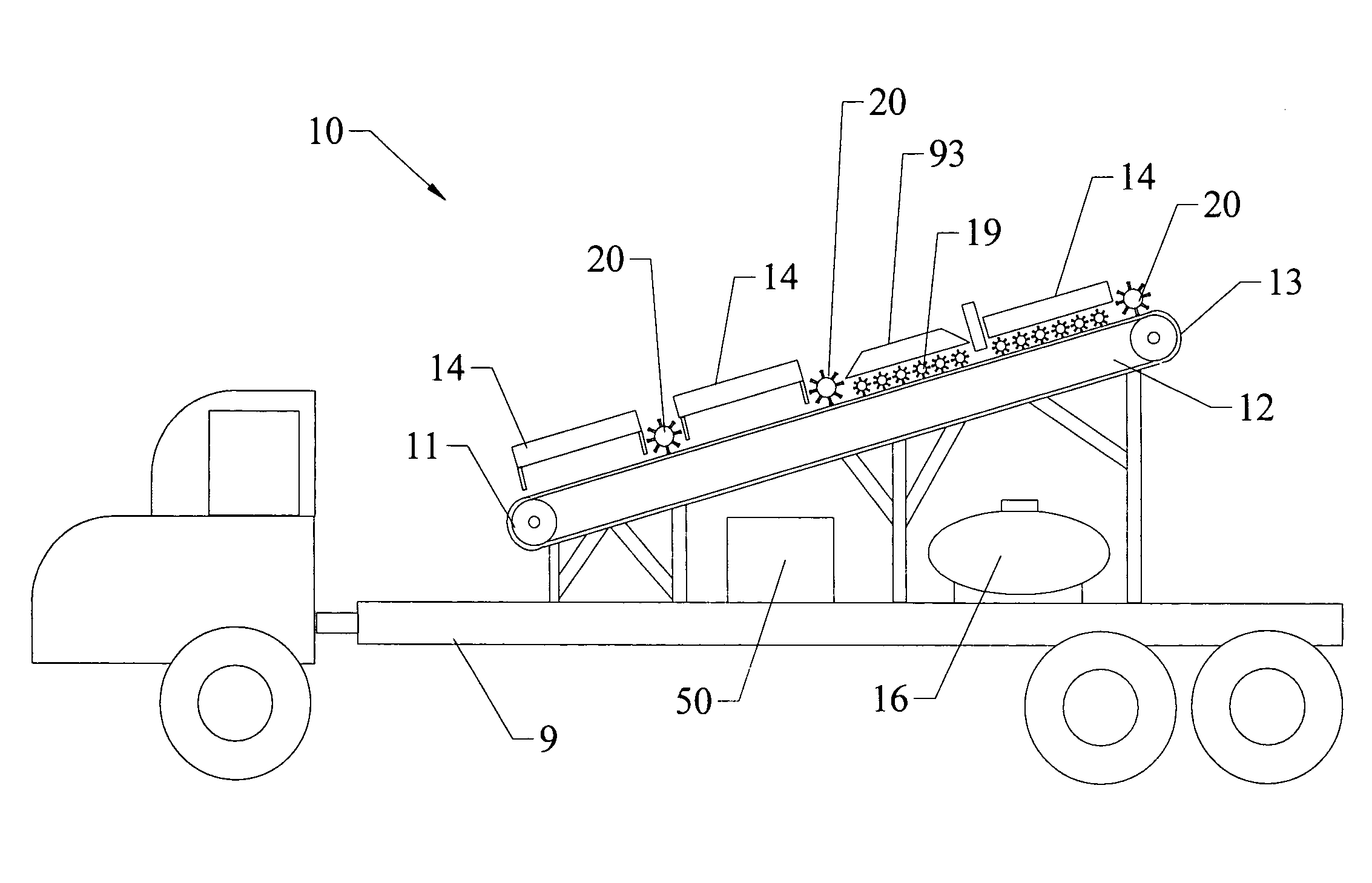
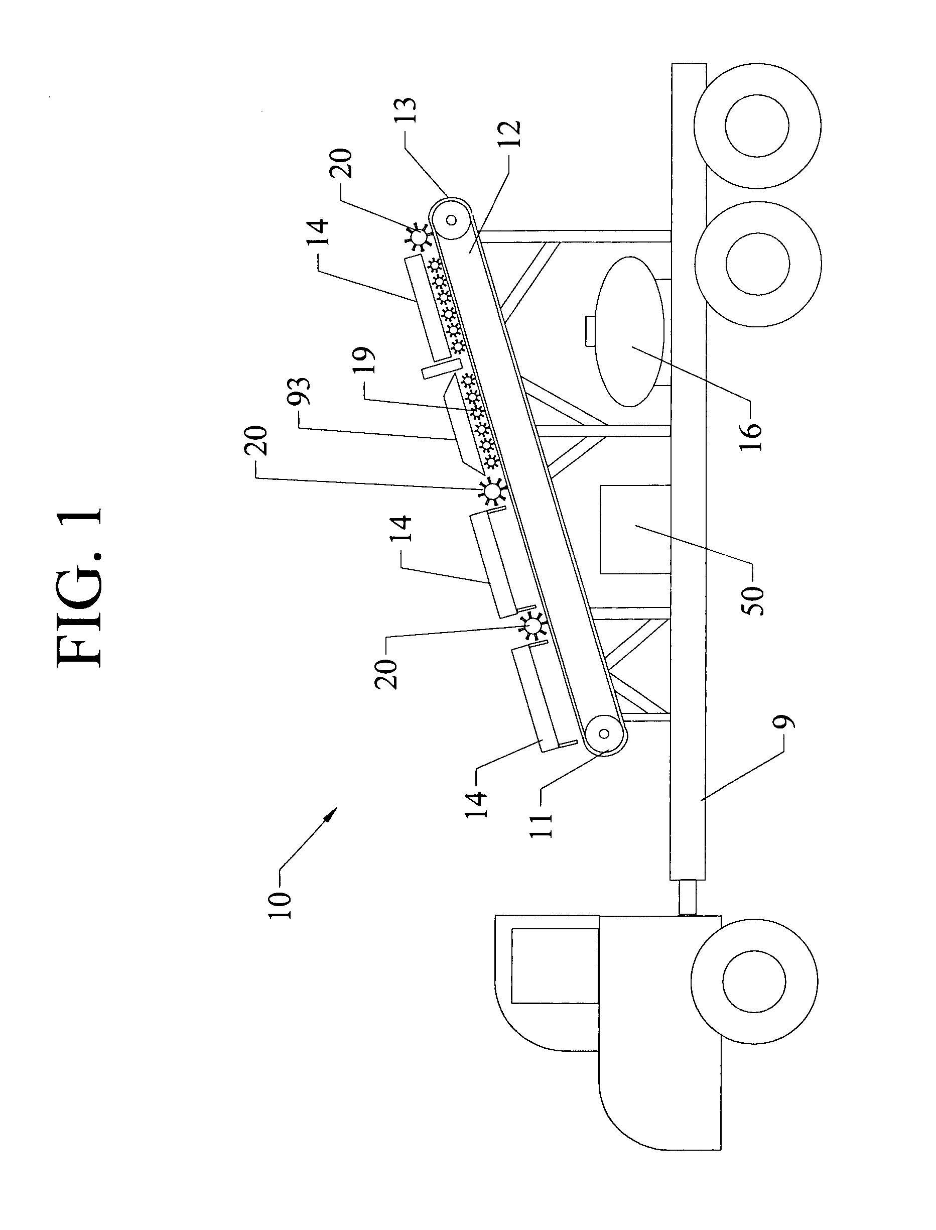
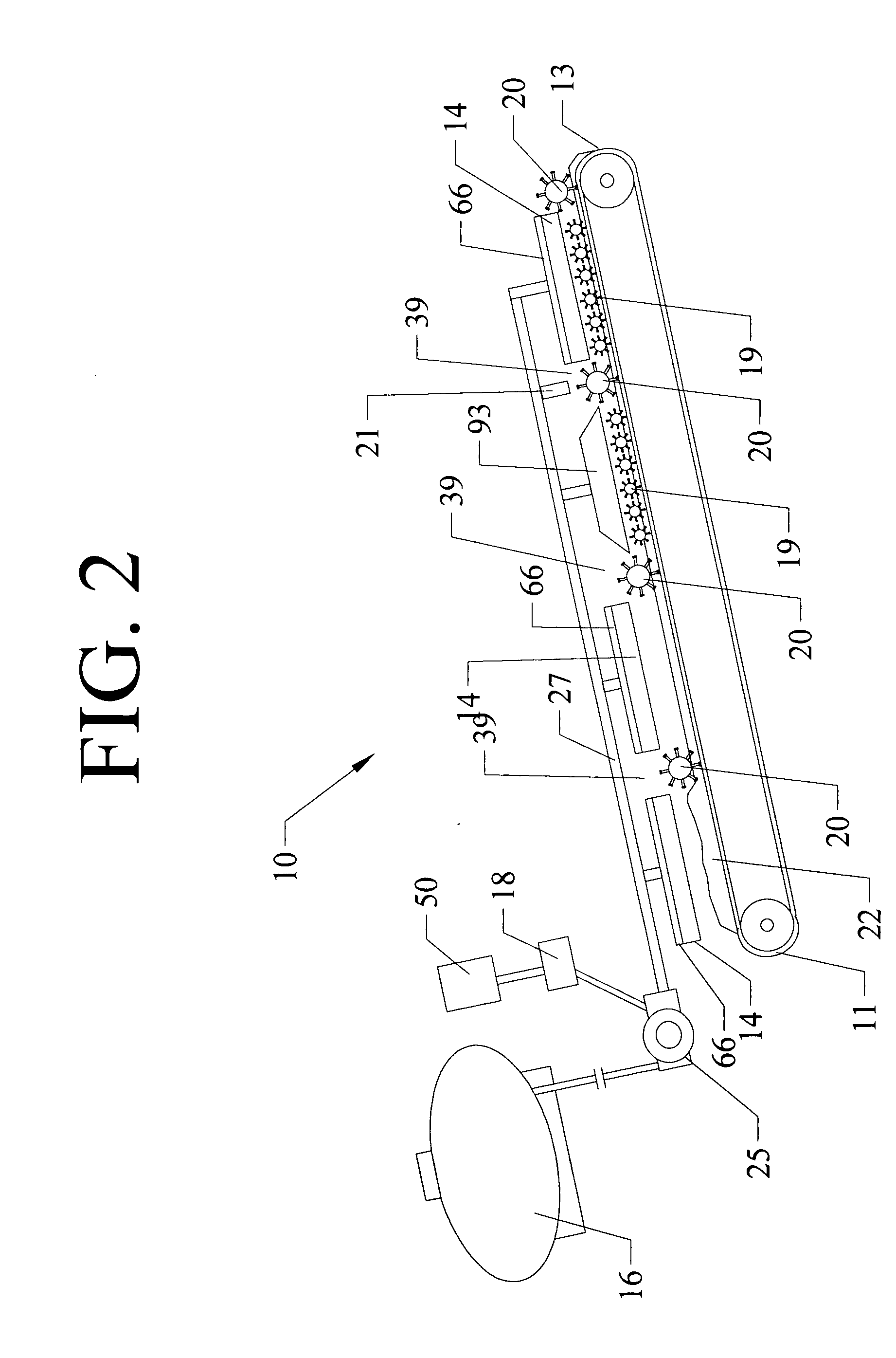
[0066]Referring to FIG. 1, a side view of one embodiment of the heating system 10 of the present invention is provided. Heating system 10 includes trailer 9, conveyor belt 12 with first and terminal ends 11, 13 respectively, infrared chambers 14, source of fuel 16, large mixers 20, small mixers 19, heat reflector 93, temperature sensor 21, and source of power 50.

[0067]Trailer 9 is preferably a 50′ trailer, but may be smaller or larger depending on the size of the conveyor belt 12 and number of infrared chambers 14 included in the heating system 10 being utilized. In addition, for heating systems 10 that include many infrared chambers 14, more than one trailer 9 may be utilized and aligned with one another.

[0068]FIG. 1 depicts a heating system 10 including a conveyor belt 12 long enough so that there is space for four infrared chambers 14 above it. It is understand that there may be fewer or greater infrared chambers 14 in other embodiments of heating system 10. Further, although fiv...


PUM

PropertyMeasurementUnit
lengthaaaaaaaaaa
diameteraaaaaaaaaa
lengthaaaaaaaaaa

Abstract

A portable system for heating aggregate material, especially reclaimed asphalt pavement (RAP), a portable system for producing asphalt, a portable system for continuously repaving roadway, and a method for continuously repaving roadway. Each system includes a conveyor belt, at least one infrared chamber disposed in substantially parallel relation to the conveyor belt at a distance sufficient to allow infrared heating of the aggregate material, a source of fuel, a fuel control in communication with the infrared chamber, and at least one mixer disposed between the infrared chamber and the conveyor belt and dimensioned and disposed relative to the conveyor belt so as to mix the aggregate material during heating and drying.

Description

CLAIM OF PRIORITY[0001]This application is a continuation in part of co-pending U.S. Non-Provisional patent application Ser. No. 11 / 805,021, filed on May 22, 2007, and claims the benefit of priority of U.S. Provisional Patent Application Ser. No. 60 / 802,360, filed on May 22, 2006.FIELD OF THE INVENTION[0002]The present invention relates to the field of asphalt manufacturing and, in particular, to a portable reclaimed asphalt pavement (RAP) pre-heating system for pre-heating RAP being conveyed into asphalt manufacturing modules during the asphalt manufacturing process.BACKGROUND OF THE INVENTION[0003]The creation and maintenance of millions of miles of roads depend on asphalt production. Most asphalt production is performed in asphalt plants or factories from whence the asphalt is transported to the pavement site. In many cases, this involves significant distances, while transporting heavy materials, such as silos to store the asphalt and the asphalt itself. Especially for longer dis...

Claims


Application Information

Patent Timeline
Patent Type & Authority Applications(United States)
IPC IPC(8): E01C23/14B28C5/34B02C11/08E01C7/00E01C21/00E01C23/12
CPCB01F13/0013B28C7/003F26B19/005F26B3/305F26B17/045E01C23/065Y02A30/30B01F33/26
Inventor VAN VELSOR, WESLEY
Owner VAN VELSOR WESLEY
Why Eureka
Eureka Blog
Learn More