Bronchial flow control devices and methods of use

a technology of bronchial flow and control device, which is applied in the field of lung disease treatment, can solve problems such as the collapse of the targeted lung region, and achieve the effect of improving the air flow dynami

Inactive Publication Date: 2011-06-02
PULMONX
View PDF101 Cites 104 Cited by
  • Summary
  • Abstract
  • Description
  • Claims
  • Application Information

AI Technical Summary

Benefits of technology

[0011]When implanted in the bronchial passageway, the flow control device can eliminate air flow into the targeted lung region and result in collapse of the targeted lung region. As an alternative to eliminating air flow and collapsing the targeted lung region, the flow control device can permit a regulated airflow to and from the targeted lung region to achieve an improved air flow dynamic that does not result in collapse of the targeted lung region.

Problems solved by technology

When implanted in the bronchial passageway, the flow control device can eliminate air flow into the targeted lung region and result in collapse of the targeted lung region.

Method used


Image

  • Bronchial flow control devices and methods of use
  • Bronchial flow control devices and methods of use
  • Bronchial flow control devices and methods of use

Examples


Embodiment Construction

[0091]Unless defined otherwise, all technical and scientific terms used herein have the same meaning as is commonly understood by one of skill in the art to which the invention(s) belong.

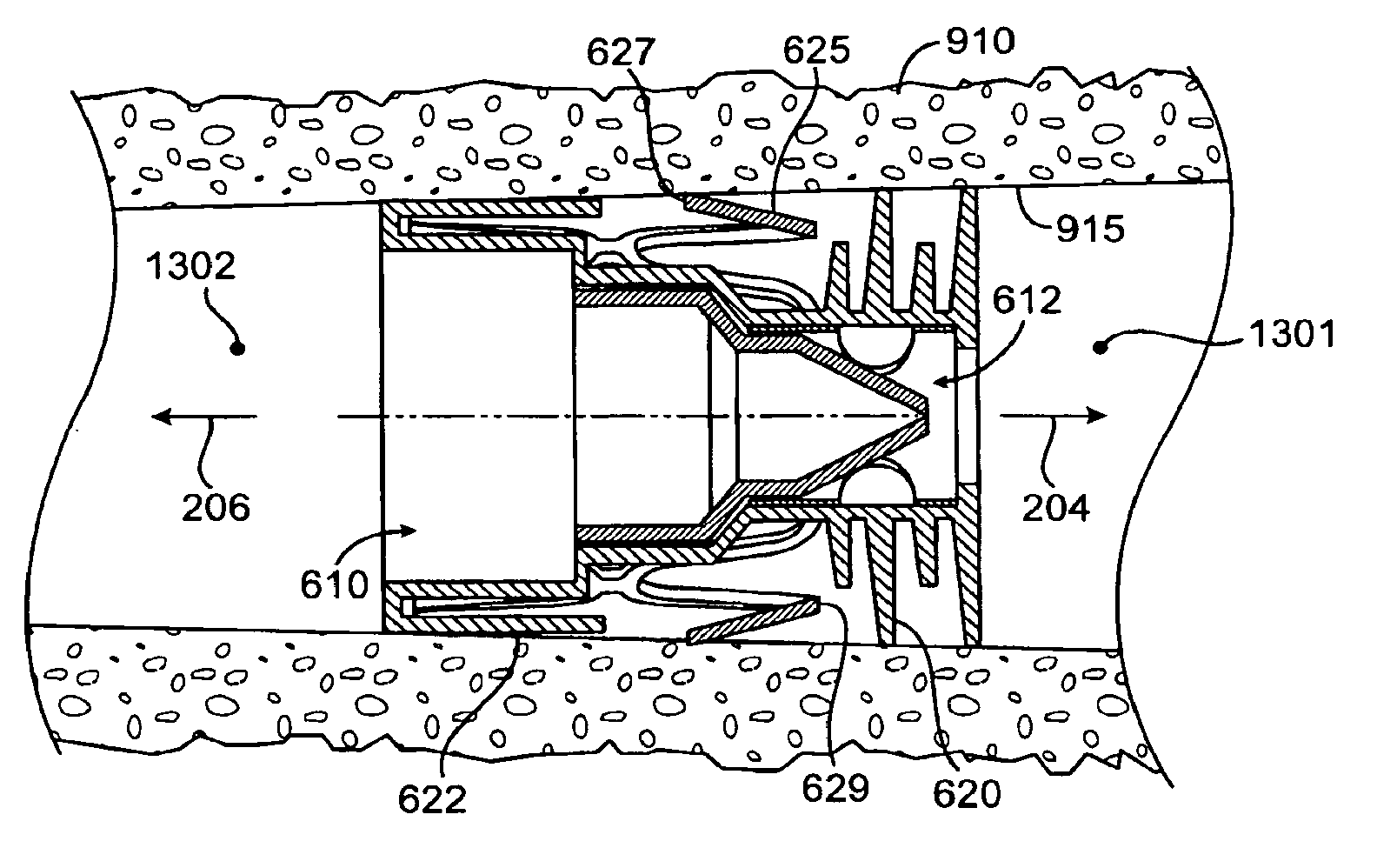
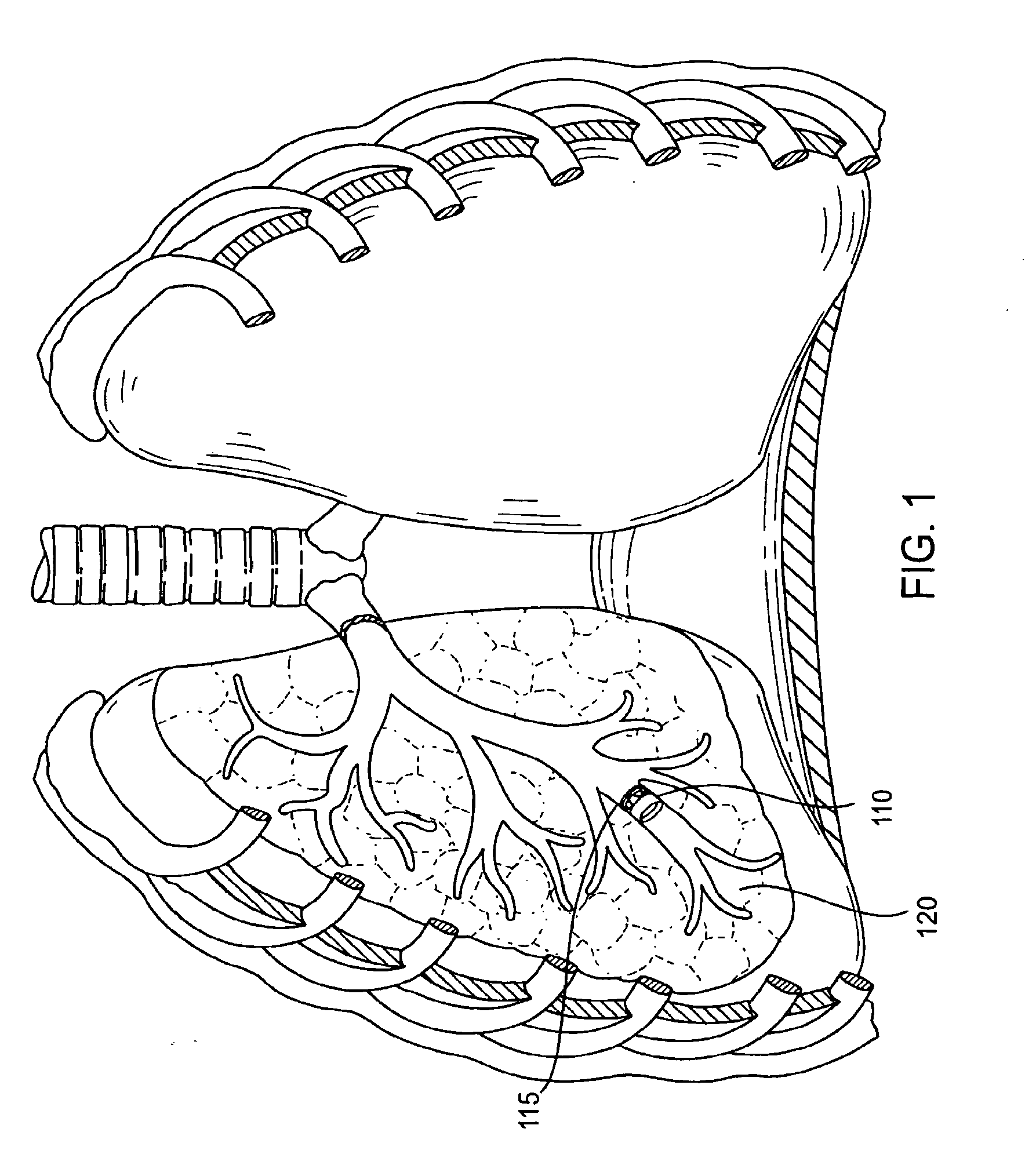
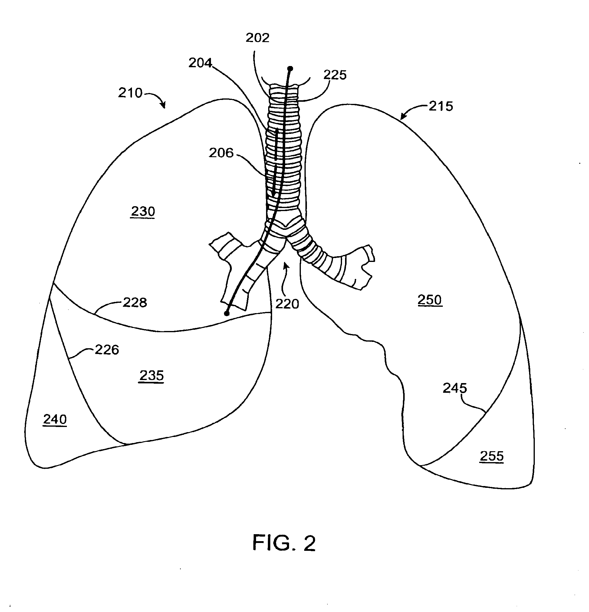
[0092]Disclosed are methods and devices for regulating fluid flow to and from a region of a patient's lung, such as to achieve a desired fluid flow dynamic to a lung region during respiration and / or to induce collapse in one or more lung regions. An identified region of the lung (referred to herein as the “targeted lung region”) is targeted for treatment, such as to modify the air flow to the targeted lung region or to achieve volume reduction or collapse of the targeted lung region. The targeted lung region is then bronchially isolated to regulate airflow into and / or out of the targeted lung region through one or more bronchial passageways that feed air to the targeted lung region. As shown in FIG. 1, the bronchial isolation of the targeted lung region is accomplished by implanting a flow control d...


PUM


Abstract

Methods and systems for lung volume reduction of a patient are described. The methods include implanting a flow control device in a bronchial passageway of the lung. The flow control device regulates fluid flow through the bronchial passageway and includes a valve protector that at least partially surrounds a valve member. The valve protector has sufficient rigidity to maintain the shape of the valve member against compression.

Description

CROSS-REFERENCES TO RELATED APPLICATIONS[0001]This application is a continuation of U.S. patent application Ser. No. 11 / 092,123, filed Mar. 28, 2005, which is a continuation of U.S. patent application Ser. No. 10 / 270,792, filed Oct. 10, 2002, which claims priority of the following co-pending U.S. provisional patent applications: (1) U.S. Provisional Patent Application Ser. No. 60 / 329,249, filed Oct. 11, 2001; (2) U.S. Provisional Patent Application Ser. No. 60 / 350,106, filed Oct. 19, 2001; (3) U.S. Provisional Patent Application Ser. No. 60 / 338,508, filed Nov. 5, 2001; (4) U.S. Provisional Patent Application Ser. No. 60 / 351,084, filed Jan. 22, 2002; (5) U.S. Provisional Patent Application Ser. No. 60 / 371,634, filed Apr. 9, 2002; (6) U.S. Provisional Patent Application Ser. No. 60 / 384,247. Priority of the aforementioned filing dates is hereby claimed, and the disclosures of the aforementioned patent applications are hereby incorporated by reference in their entirety.BACKGROUND OF THE...

Claims


Application Information

Patent Timeline
Patent Type & Authority Applications(United States)
IPC IPC(8): A61F2/04A61B17/00A61B17/24A61F2/06A61F2/24A61M16/00A61M16/20
CPCA61F2/04A61F2/06A61F2/2412A61F2/2418Y10S128/912A61F2/91A61F2002/043A61F2002/9522A61B2017/1205A61F2/2427A61F2/9522
Inventor WILSON, PETER M.FIELDS, ANTONY J.GIFFORD, III, HANSON S.MCCUTCHEON, JOHN G.HENDRICKSEN, MICHAEL J.RAPACKI, ALAN R.THOLFSEN, DAVID R.BARRETT, MICHAEL S.HUNDERTMARK, RONALDSUTTON, DOUGLAS
Owner PULMONX
Why Eureka
Try Eureka